Introduction
Relay modules can be used to control inductive loads such as solenoid valves, motors, pumps, contactors, and electromagnetic actuators. These loads require special consideration because they can generate a voltage spike when the relay switches them OFF.
This article explains how to connect and protect inductive loads when using SPST and SPDT relay modules.
SPST Relay Connection
The SPST relay module provides two load-side terminals:
- IN – Input side of the load circuit
- OUT – Output side of the load circuit
When the relay is OFF, the IN and OUT terminals are disconnected.
When the relay is ON, the IN and OUT terminals are electrically connected.
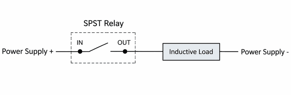
This arrangement is suitable when the load needs to be switched ON and OFF.
SPDT Relay Connection
An SPDT relay provides three contacts:
- COM – Common
- NO – Normally Open
- NC – Normally Closed
When the relay is OFF:
COM ─── NCWhen the relay is ON:
COM ─── NOA typical connection can be used to select between two circuits:
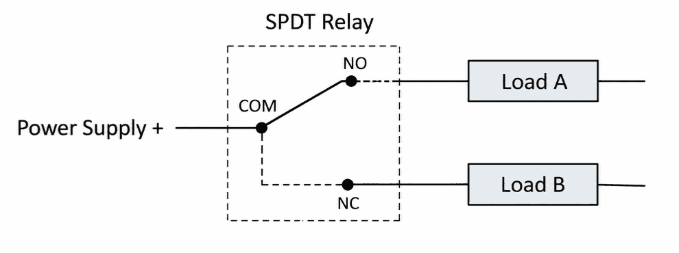
This makes SPDT relays useful when an application requires changeover control, rather than simply switching one load ON and OFF.
Controlling DC Inductive Loads
For DC inductive loads such as solenoid valves and DC contactors, a flyback diode can be connected across the load.
Example
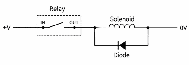
The diode is reverse-biased during normal operation.
For a positive supply:
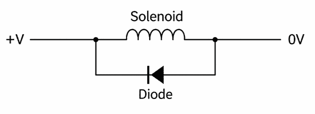
The cathode of the diode should be connected toward the positive side of the load, and the anode toward the negative side.
When the relay is ON, the diode remains inactive. When the relay switches OFF, the diode provides a path for the energy stored in the inductive load.
Important
The diode must be selected based on the load’s operating voltage and current. The diode rating should be suitable for the actual application.
Controlling AC Inductive Loads
A standard flyback diode should not be connected directly across an AC load.
For AC inductive loads such as AC motors, contactors, and solenoids, an appropriately rated MOV or RC suppression circuit can be used.
A suppression device can be connected across the load:
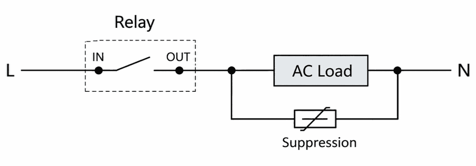
The suppression component must be selected according to the load voltage and application.
For mains-powered loads, use components specifically rated for the applicable voltage and safety requirements.
Using an SPDT Relay for Inductive Loads
When using an SPDT relay to control inductive loads, the suppression method depends on the loads connected to the NO and NC contacts.
If both loads are inductive, each load should have suitable suppression.
For DC loads:
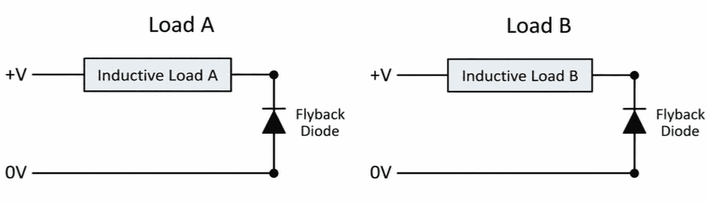
This helps prevent the switching transient from one load from unnecessarily stressing the relay contacts.
Safety Considerations
Before connecting an inductive load, check the relay’s contact specifications.
Consider:
- Load voltage
- Load current
- Starting or inrush current
- AC or DC operation
- Type of inductive load
- Switching frequency
- Required relay life
The current drawn during normal operation may be lower than the current drawn when the load starts. This is particularly important for motors and other loads with high starting current.
Do not select a relay based only on the nominal load current.
When controlling inductive loads using relay modules:
- Do not exceed the relay’s specified contact ratings.
- Consider the load’s starting or inrush current.
- Use suitable suppression for inductive loads.
- Verify the polarity when using a DC flyback diode.
- Use appropriately rated components for AC loads.
- For mains-voltage applications, follow appropriate electrical safety practices.
- Use suitable fusing and protection for the external load circuit.
- Ensure that wiring, connectors, insulation, and enclosure are suitable for the operating voltage and current.
SPST and SPDT relay modules can both be used to control inductive loads.
Because inductive loads can generate voltage transients when switched OFF, using an appropriate suppression method is important for reliable relay operation and longer contact life.
For DC inductive loads, a correctly connected flyback diode is a simple and effective solution. For AC inductive loads, use an appropriately rated suppression device such as an MOV or RC circuit.