
Introduction
| Sl.No. | SKU | Description | Relay Type | Operating temperature |
|---|---|---|---|---|
| 1 | NLEWR008A | LEO WR 8 Channel Web Relay Module - WR8A | SPST | -40 ℃ to 85 ℃ |
| 2 | NLEWR008A-24 | LEO WR 8 Channel Web Relay Module - WR8A-24 | SPST | -40 ℃ to 85 ℃ |
| 3 | NLEWR008B | LEO WR 8 Channel Web Relay Module - WR8B | SPDT | -40 ℃ to 85 ℃ |
| 4 | NLEWR008B-24 | LEO WR 8 Channel Web Relay Module - WR8B-24 | SPDT | -40 ℃ to 85 ℃ |
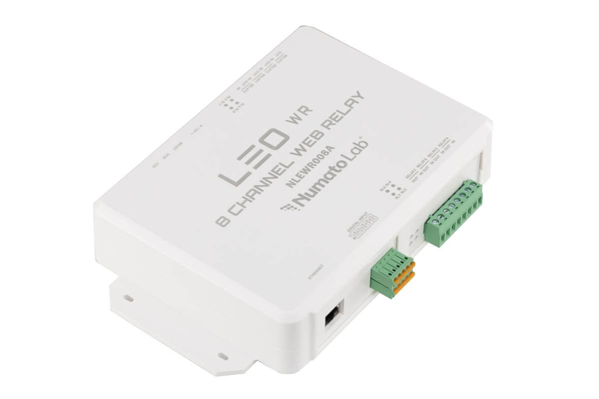
Note: In this document, “LEO WR8” refers to the LEO WR 8 Channel Web Relay Module.
The Numato Lab LEO WR 8 Channel Web Relay Module is a compact, network-enabled controller designed for remote control and monitoring of electrical and electronic devices.
The LEO WR8 provides 8 relay channels and high-voltage digital inputs supporting up to 24 V, with Ethernet and 2.4 GHz Wi-Fi connectivity.
The module supports multiple communication methods depending on the network interface:
- Ethernet: Web interface, REST API, and Telnet
- Wi-Fi: Web interface, REST API, and MQTT/MQTTS
The MQTT/MQTTS support allows the LEO WR8 to connect to MQTT-compatible cloud platforms and IoT services. Once connected, these platforms can be used to remotely monitor the device and control its relays, enabling integration with cloud-based automation systems.
With its flexible connectivity and easy-to-use interfaces, the LEO WR8 is suitable for industrial automation, IoT applications, remote equipment control, testing, and smart automation systems. Users can operate the device through the web interface or integrate it into custom applications using REST API, Telnet, or MQTT/MQTTS.
Applications
- Industrial Automation: Monitor sensor inputs and control actuators, machines, or alarms based on configurable logic.
- Smart Home & Building Automation: Automate lighting, HVAC systems, and appliances using environmental data and remote control.
- IoT & Cloud-Based Monitoring: Stream real-time data to AWS, Azure, or private MQTT brokers for centralized dashboards and alerting.
- Remote Control Systems: Operate devices from anywhere using the onboard web server or REST APIs.
- Smart Agriculture: Monitor field conditions and control irrigation or other systems based on environmental triggers.
- Test Fixtures
- DIY and Hobby
Key Features
- 8 Relay Outputs: Available in SPST and SPDT variants. Relay contact ratings depend on the installed relay variant.
- 8 High-Voltage Digital Inputs: Supports input voltages of up to 24 V for monitoring external signals and equipment.
- Relay Status LEDs: Individual LEDs indicate the status of each relay on SPST relay variants.
- Standalone Rule-Based Automation: Create local automation rules to automatically control relays based on input conditions and configured events, without requiring a host PC or cloud connection.
- Smart Relay Control: Provides intelligent relay control based on configured conditions, inputs, and automation rules.
- Relay Timer: Configure relays to turn ON or OFF automatically for a specified duration or at configured intervals.
- Fail-Safe Operation: Configure predefined relay states and actions to maintain safe and predictable operation during communication or system failures.
- Ethernet Connectivity: Provides reliable wired network connectivity for device access and control.
- 2.4 GHz Wi-Fi: Provides wireless connectivity for remote monitoring and control.
- Web Interface: Built-in password-protected web interface for device configuration, monitoring, and relay control.
- REST API: Enables integration with custom software and automation applications over Ethernet and Wi-Fi.
- Telnet Interface: Provides command-line access for relay control and device configuration over Ethernet.
- MQTT/MQTTS Support: Enables integration with MQTT-compatible IoT and cloud platforms for remote monitoring and control over Wi-Fi.
- Cloud Integration: Supports cloud platforms and services that use MQTT/MQTTS, including AWS, Microsoft Azure, and other MQTT-compatible platforms.
- DIN Rail Mounting: Supports standard DIN rail installation for convenient deployment in control panels and industrial environments.
- USB Connectivity: Provides local access and configuration without requiring a network connection.
- RGB Status Indicator: Provides a quick visual indication of the device’s operating status.
Technical Specifications
| Parameter* | Value | Unit | |||
|---|---|---|---|---|---|
| Variant | NLEWR008A | NLEWR008A-24 | NLEWR008B | NLEWR008B-24 | |
| Basic Specifications | |||||
| Number of relays | 8 | 8 | 8 | 8 | |
| Number of Digital Inputs | 8 | 8 | 8 | 8 | |
| Digital circuit power supply voltage (External) | 12 | 24 | 12 | 24 | V |
| Maximum current drawn by digital circuitry | 300 | 300 | 300 | 300 | mA |
| Digital Inputs Specifications | |||||
| Minimum DI sink current | 2.05 | 2.05 | 2.05 | 2.05 | mA |
| Maximum DI sink current | 30 | 30 | 30 | 30 | mA |
| Recommended sink current | 10 | 10 | 10 | 10 | mA |
| Maximum Low Voltage (VIL) | 10.2 | 10.2 | 10.2 | 10.2 | V |
| Minimum High Voltage (VIH) | 10.5 | 10.5 | 10.5 | 10.5 | V |
| Maximum High Voltage | 24 | 24 | 24 | 24 | V |
| Relay Specifications | |||||
| Nominal relay coil voltage | 12 | 24 | 12 | 24 | V |
| Nominal coil power consumption (per relay) | 450 | 450 | 450 | 450 | mW |
| Relay contact material | Silver Alloy, silver metal-oxide | Silver Alloy, silver metal-oxide | silver metal-oxide | silver metal-oxide | |
| Contact rating | 7A 250VAC 7A 28VDC | 7A 250VAC 7A 28VDC | 7A/ 277V AC 7A/ 28V DC | 7A/ 277V AC 7A/ 28V DC | |
| Maximum switching voltage | 250VAC/30VDC | 250VAC/30VDC | 277VAC/28VDC | 277VAC/28VDC | |
| Maximum switching current | 7 | 7 | 7 | 7 | A |
| Maximum switching power | 2500VA/300W | 2500VA/300W | 2770VA/ 196W | 2770VA/ 196W | |
| Contact resistance | 100 | 100 | 100 | 100 | mΩ (at 1A 6VDC) |
| Insulation resistance | 1000 | 1000 | MΩ | ||
| Life expectancy (Electrical) | 100000 | 100000 | 100000 | 100000 | Operations (at 7A 250VAC resistive load, room temp) |
| Life expectancy (Mechanical) | 10000000 | 10000000 | 10000000 | 10000000 | Operations |
| Maximum switching on response time | 1 | 1 | 1 | 1 | second |
| Maximum switching off response time | 9 | 9 | 9 | 9 | second |
| shock resistance (Functional) | 294 | 294 | 98 | 98 | m/s2 |
| Shock resistance (Destructive) | 980 | 980 | 980 | 980 | m/s2 |
| Vibration resistance | 10Hz to 55Hz, 1.5mm DA | 10Hz to 55Hz, 1.5mm DA | 10Hz to 55Hz, 1.5mm DA | 10Hz to 55Hz, 1.5mm DA | |
| Relay Indication | Available | Available | Not Available | Not Available | |
* All parameters considered nominal. Numato Systems Pvt Ltd reserve the right to modify products without notice.
* SPST Variant Datasheet – HF32FV-G Relay
* SPDT Variant Datasheet – HF3FF Relay
Note: Relay ratings are based on the relay manufacturer’s specifications. Actual allowable load depends on load type, switching frequency, ambient conditions, wiring, and the complete module design. Refer to the relay datasheet and application guidelines before switching loads near the maximum rating.
How to use the module
The following section describes how to use this module.
Components/Tools required
Along with the module, you may need the items in the list below for easy and fast installation.
- CAT 5e Ethernet Cable(Straight through cable)
- 12V/24V 1A DC power supply, depending on the relay variant
- USB Type C Cable
- Medium-sized Philips screwdriver
Connection Details

DC Power Supply
 This board can be operated using a single DC power supply. Depending on the relay variant, connect either a 12V/24V DC, 1A power supply to the DC jack on the board. The power supply provides power to both the logic circuitry and the relays.
Connecting the power supply incorrectly can cause damage to the module and/or other devices.
USB Interface
The LEO WR 8 Channel Web Relay Module is designed for quick and intuitive operation. With its human-readable command set and standard USB CDC interface, the device can be used with widely available serial terminal applications, with no specialised software required.
It is compatible with most common terminal tools, including:
- Windows
- Tera Term
- PuTTY
- Linux
- GNU Screen
- PuTTY
- MAC OS X
- Screen Command
- CoolTerm
Note: The device is not limited to the above tools and can be used with any standard serial terminal software.
Getting started with the device involves just a few simple steps:
- Connect the Device: Plug the module into a USB port on your host system.
- Install Drivers (Windows Only): The driver is available on the product page.
- Open the COM Port: Open the COM Port assigned to the device using your preferred serial terminal software.
- Configure the Device: Configure the device with simple human-readable commands, similar to using DOS or a Bash terminal.
- Automate via scripts: Integrate with your application or scripts using a language of choice such as C, Python, Node.js, Perl, or others.
- Enable Standalone Automation: Configure Smart Actions and Relay Timers to allow the device to operate independently without a host system.
Use a USB-A to USB-C/ USB-C to USB-C cable to connect to a PC. Please visit accessories to buy cables and accessories for this product.
Ethernet Connectivity

The LEO WR8 features a 10/100 Mbps Ethernet interface, providing network communication speeds of up to 100 Mbps for communication and control of the module.
The module can be connected directly to a computer or to a Local Area Network (LAN) using a standard Ethernet cable.
Example: Connect the LEO WR8 to a network switch using an Ethernet cable to access and control the module from computers or other devices on the same network.
Note: Actual data throughput may vary depending on the network configuration, communication protocol, packet size, and other network conditions.
Wi-Fi Connectivity
The LEO WR8 features built-in 2.4 GHz Wi-Fi for wireless network connectivity, allowing the module to be accessed and controlled without a wired Ethernet connection.
The module supports Wi-Fi Station (STA) mode, allowing it to connect to an existing wireless network. Wi-Fi network settings can be configured through the module’s web interface or USB connection, without requiring additional hardware.
Once connected to the network, the LEO WR8 can be accessed through its web interface and REST API for configuration, monitoring, and control. The module also supports MQTT/MQTTS, allowing relay and device data to be exchanged with MQTT-compatible applications and cloud platforms for remote monitoring and control.
Wi-Fi connectivity makes the LEO WR8 suitable for wireless automation, remote equipment control, IoT applications, and cloud-connected systems.
Relay Contacts
The LEO WR8 is available in SPDT and SPST relay variants. The relay contacts are accessible through the onboard screw terminals for easy connection to external loads.
SPDT Variant – [WR8B, WR8B-24]
The WR8B and WR8B-24 models are equipped with 8 SPDT relays. Depending on the relay variant, the relays are available in 12 V or 24 V coil versions and support switching currents of up to 7 A, subject to the applicable relay specifications.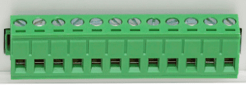
Each SPDT relay provides three contacts:
- COM (Common): Common relay contact
- NO (Normally Open): Connected to COM when the relay is ON
- NC (Normally Closed): Connected to COM when the relay is OFF
When the relay is OFF, COM is connected to NC. When the relay is ON, COM is connected to NO.
The table below shows the relay contact states:
| Relay State | Connection between NC and C | Connection between NO and C |
|---|---|---|
| OFF | Close | Open |
| ON | Open | Close |
SPST Variant – [WR8A, WR8A-24]
The WR8A and WR8A-24 models are equipped with 8 SPST relays. Depending on the relay variant, the relays are available in 12 V or 24 V coil versions and support switching currents of up to 7 A, subject to the applicable relay specifications.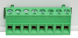
Each SPST relay provides two contacts:
- IN: Input contact
- OUT: Output contact
When the relay is ON, the IN and OUT contacts are connected. When the relay is OFF, the connection between IN and OUT is open.
The table below shows the relay contact states:
| Relay State | IN to OUT Connection | Load Condition |
|---|---|---|
| OFF | Open | Load Disconnected |
| ON | Closed | Load Energized |
Digital Input Contacts
In addition to the onboard relays, the LEO WR 8 Channel Web Relay Module features 8 high-voltage digital input channels, designed for reliable interfacing with external signals in industrial environments.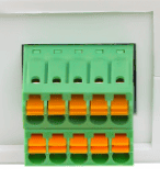
Input Voltage Range
- Recommended Operating Voltage: Up to 24V
- Logic LOW (Max): <= 10.2V
- Logic HIGH (Min): >= 10.5V
Input Current Characteristics
- Minimum Sink Current: 2.05 mA
- Maximum Sink Current: 30 mA
Each input channel detects the presence of an external voltage signal and interprets it as a digital HIGH or LOW based on the defined thresholds. These inputs can be used to monitor signals from switches, sensors or any other control systems.
Important Notes
- Ensure input voltages remain within the specified limits to prevent damage.
- Always use proper grounding and wiring practices in industrial environments.
LED Indication
The LEO WR 8 Channel Web Relay module provides visual feedback through the onboard LED indicator:
- On Power-On
- Device Reset
- Factory Reset
- Network Status
| LED Indication | Status |
|---|---|
| Solid Red | USB configuration mode |
| Blinks in Blue Colour | Trying to connect to network |
| Solid Purple | Connected to Ethernet network |
| Solid Turquoise Blue | Connected to Wi-Fi network |
| Solid Blue | Connected to both Ethernet and Wi-Fi |
| Blinks in Red Colour | Factory reset in progress |
Multipurpose Switch
The LEO WR 8 channel Web Relay Module is equipped with a versatile multipurpose switch that enables a range of device management functions:
| Action | LED Indication | Function |
|---|---|---|
| Single Click | The Red LED briefly turns OFF and ON, indicating that the device is restarting. | Device Reset: Resets the device and reinitializes. |
| Press for 7-10 seconds | The Red LED blinks continuously while the factory reset process is in progress. | Factory Reset: Device erases all the settings and restores to factory defaults. |
Important: Factory reset restores the device to its factory-default configuration and erases all user-configured settings, including network, MQTT, Smart Action, Timer, Fail-Safe, Device ID, username, and password settings. Use the Factory reset feature only to recover the Username/Password/Hostname or when you need to restore the device to its factory-default state.
Factory Reset
The LEO WR 8 Channel Web Relay Module provides a factory reset feature to restore all settings to their original default values.
How to Perform a Factory Reset
You can initiate a factory reset using either of the following methods:
- Using the Multipurpose Switch: Press and hold the RESET switch for 7 – 10 seconds.
- Using Command Interface: Execute the factory reset command via the USB console.
Important Notes
- This operation will reset all user-configured settings, including:
- Username and Password
- Device ID
- Smart Actions and Timer configurations
- All other user-configured parameters.
- After reset, the device will revert to factory default credentials, as listed in the table below.
Factory Default Settings
The default configuration after a factory reset is provided in the table below.
| User name | admin |
| Password | admin1234 |
| Host Name - both net0 and net1 | *Factory set default unique Hostname. |
| Device ID | 00000000 |
| net0 IP Address | 169.254.1.1 |
| Telnet Authentication | ON |
| Telnet Port | 23 |
| net1 IP Address | 169.254.1.1 |
| Access IP - both net0 and net1 | Disabled |
| IP0 to IP9 | 255.255.255.255 |
| DHCP Status - both net0 and net1 | Enabled |
| Smart Action | Disabled |
| Relay Power-On | Disabled |
| GPI Notify Feature | Disabled |
| IO Fail-Safe | Idle |
Powering up LEO WR8 after Factory Reset
For a factory-reset device, the recommended configuration sequence is:
Power ON – Connect USB – Log in – Configure Network – Connect to Ethernet/Wi-Fi – Access Web Interface – Configure Application Features
After the network configuration is complete, USB is not required for normal operation. The module can be accessed and controlled through the available network interfaces.
Note: The exact configuration options available through USB, the Web Interface, and network interfaces may vary depending on the firmware version.
Smart Action Engine
The Smart Action Engine enables real-time, rule-based automation by directly mapping digital inputs to relay outputs. It allows the module to respond instantly to input conditions using configurable logic modes such as LOW, HIGH, or FOLLOW.
This feature transforms the device from a simple USB relay interface into an intelligent control system, capable of operating independently without continuous host intervention.
Ready to make your device smarter? Explore the Smart Action Engine command set to discover powerful automation options and enable Smart Action on your device.
Relay Timer Engine
The Relay Timer Engine provides precise time-based control of relay operations. It supports configurable modes such as Delayed ON, Delayed OFF, and Toggle, enabling automation of sequencing, scheduling, and timed switching tasks.
With persistent configuration, the timer functionality continues to operate even after power cycles, making it ideal for autonomous and repeatable control applications.
Discover the possibilities with Relay Timer Engine! Explore the Relay Timer Engine command set to learn how to unlock powerful automation and enable Smart Action on your device.
IO Failsafe Control
The IO Failsafe Control feature ensures safe and predictable system behaviour by monitoring a designated digital input. When the configured input reaches the specified trigger condition, the module automatically drives the relays to a predefined state.
This is essential for implementing safety mechanisms such as emergency shutdowns, fault handling, and enforcing defined system states based on input-triggered conditions.
Take your device automation to the next level! Refer to the IO Failsafe Control command set to explore what’s possible and get started with IO Failsafe.
Supported Error Codes
The LEO WR 8 Channel WEB Relay Module returns error codes to indicate invalid commands or incorrect parameter usage.
These codes help in quickly identifying and resolving issues during operation.
| Error Code | Error Name | Description |
|---|---|---|
| -3 | Invalid Command | The device does not recognise the entered command |
| -2 | Invalid Argument | One or more parameters are incorrect |
| -51 | Invalid Relay Timer Limit | Timer delay is outside the allowed range |
| -41 | Invalid Smart Engine Mode | The IO is already set to a different smart engine mode |
| -42 | Invalid Relay Value | The relay value is outside the allowed range in the smart action engine |
Notes:
- Error codes are returned immediately upon command validation failure
- Ensure all commands and parameters follow the defined format and limits
- Refer to individual command sections for valid parameter ranges
Powering Up LEO WR 8 Channel Web Relay Module
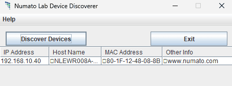
Connect a DC power supply and power up the device as mentioned in the DC Power Supply section above. An RGB LED will glow Red for 2 seconds, which indicates active power. Connect the module to a Switch/Router as mentioned in the Ethernet Interface section above. Run the Numato Lab Device Discoverer application (Numato Lab Device Discoverer.jar), and click on Discover Devices. The window will display the IP address, Host Name, MAC Address, and Other information.
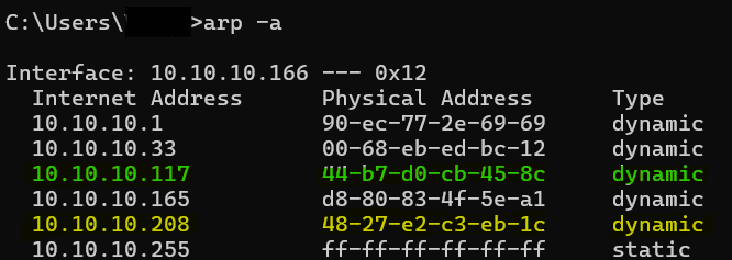
IP Address and MAC Address can also be seen in the command prompt, only after connecting the module through the web page. Open the command prompt and type the command ‘arp -a‘. This will display the available network interfaces and connected devices along with the MAC address and IP address of each device. Look for the IP address that corresponds to your device’s MAC address. The 2 MAC addresses and Hostnames for each Relay Module are printed on a label on the board for your convenience. Use the Hostname or the IP address obtained to access the device.
Device USB Mode
Configure LEO WR8 : 8 Channel Web Relay Module
Before configuring the LEO WR8, connect a suitable DC power supply and power on the module. The PWR LED will illuminate to indicate that the device is powered.
The LEO WR8 provides a USB interface for local configuration and device access. It can also be configured and operated over the network using Ethernet or 2.4 GHz Wi-Fi.
USB Configuration
USB configuration is useful for initial setup, network configuration, and local device access, especially when the module has not yet been connected to a network.
- Connect the LEO WR8 to a PC using a USB-A to USB-C or USB-C to USB-C cable.
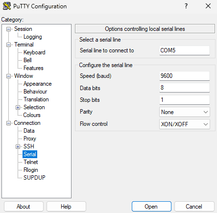
- Open a serial terminal application such as Tera Term, PuTTY, or another terminal emulator.
- Select the COM port assigned to the LEO WR8.
- Configure the terminal using the communication settings specified in the USB Interface section.
- Connect to the module.
The module will display a login prompt. Enter the appropriate credentials to access the configuration interface.
For a device with factory-default settings, use:
- Username:
admin - Password:
admin1234
After successful authentication, a login success message will be displayed, and the available USB configuration commands can be accessed.
Security Recommendation: Change the default password immediately after the first login. Do not expose the device to an untrusted network while default credentials are still enabled.
Explore the USB Configuration command set to get hands-on experience with configuring your device.
Network Configuration
Once the network settings are configured, the LEO WR8 can be connected to an existing network through Ethernet or 2.4 GHz Wi-Fi.
Depending on the network interface, the following communication methods are available:
| Interface | Available Communication |
|---|---|
| Ethernet | Web Interface, REST API, Telnet |
| Wi-Fi | Web Interface, REST API, MQTT/MQTTS |
The Web Interface provides a convenient way to configure and monitor the device through a standard web browser.
The REST API allows the LEO WR8 to be integrated with custom applications and automation software.
The Telnet interface provides command-line access to the device over Ethernet.
The MQTT/MQTTS interface allows the LEO WR8 to communicate with MQTT-compatible applications and cloud platforms for remote monitoring and control over Wi-Fi.
Discover more about your device configuration by exploring the Ethernet Configuration command set or/and Wi-Fi Configuration command set.
Device Application Mode
Accessing the module
The module can be monitored and controlled by using the interfaces below.
- Through HTML/Web Page served from the device – Ethernet interface.
- Through HTML/Web Page served from the Wi-Fi interface.
- Through a Serial terminal Emulator that supports TELNET (Eg: Hyper Terminal, TeraTerm, PUTTY…).
- Through REST API commands.
Accessing the module using Ethernet web interface
The easiest method for controlling the module is through web page served from the device. To open the administration web page, type in the IP address or hostname.local into the address bar of any web browser and press enter.
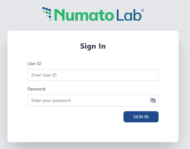
You will be prompted to enter your Username and Password. The default username is ‘admin,’ and the default password is “admin1234“. Once logged in, you may change the Username and Password.
Enter the default User name and Password, then click Sign In.
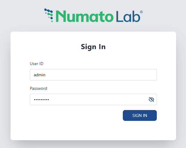
You will be presented with the device home page that shows the status of Relays and GPIs.
Get started with application through Ethernet Web Interface .
Accessing the module using Wi-Fi web interface
The easiest method for controlling the module is through a web page served from the device. To open the administration web page, type the IP address or hostname.local into the address bar of any web browser and press Enter.
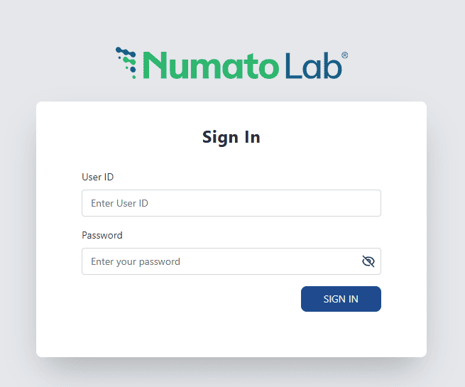
You will be prompted to enter your username and Password. The default username is ‘admin,’ and the default password is “admin1234“. Once logged in, you may change the Username and Password.
Enter the default username and password, then click Sign In.
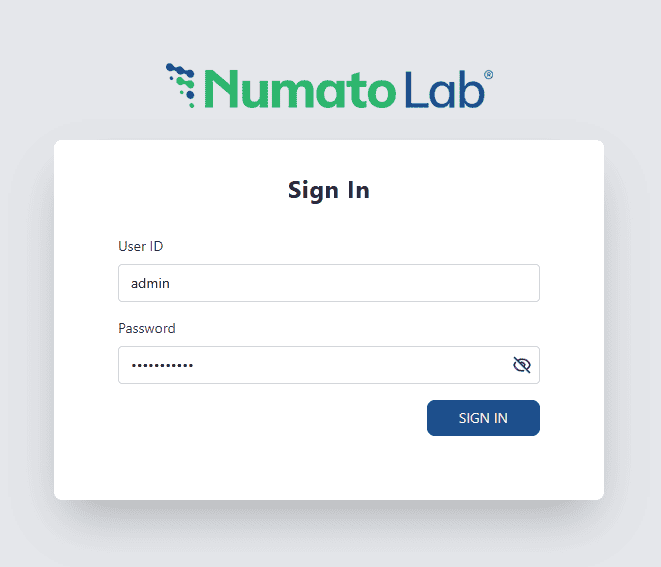
You will be presented with the device home page that shows the status of Relays and GPIs.
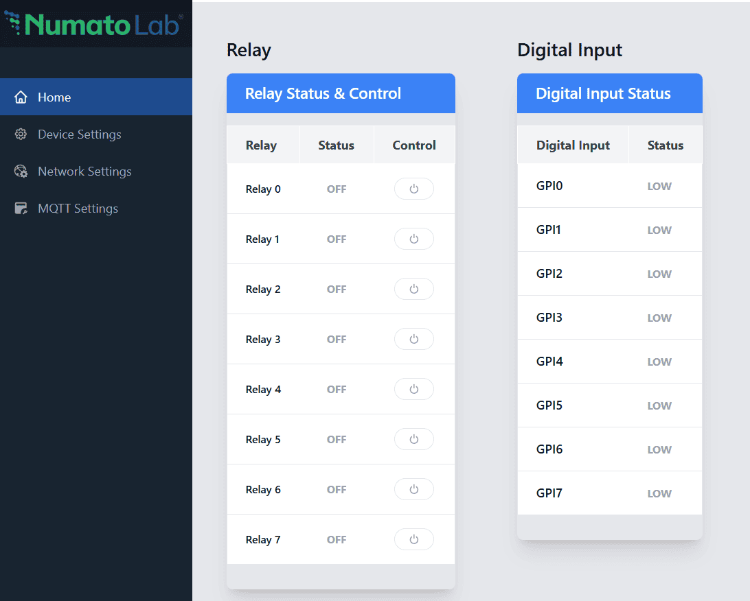
Get started with application through Wi-Fi Web Interface .
Controlling the module through Telnet interface
The simple, human-readable ASCII command set makes it easy to control the relays through the Telnet interface. The following sections give examples of how to use the module with PuTTY and TeraTerm.
To use this module with PuTTY, please follow the steps below.
- Connect the module to the LAN.
- Open PuTTY and enter the IP address corresponding to the module, leaving the port number as 23.
- Click Open.
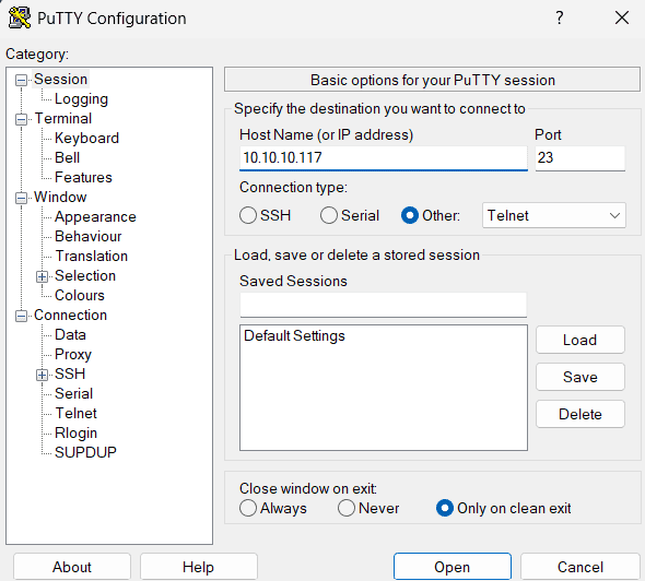
- If everything goes well, you should be presented with a screen as below.
- Type in the TELNET User name and Password when asked and press enter key.
- Commands listed in the table in section “Sending Commands” can be entered here now. For example, here is the response for “ver” command.
- Using the relay module with TeraTerm is just as easy. Please follow the steps below.
TeraTerm is an open source software. A free copy can be downloaded from http://en.sourceforge.jp/projects/ttssh2/releases/.
- Run TeraTerm and type in the IP address corresponding to the module in the “New connection” dialog and click OK.
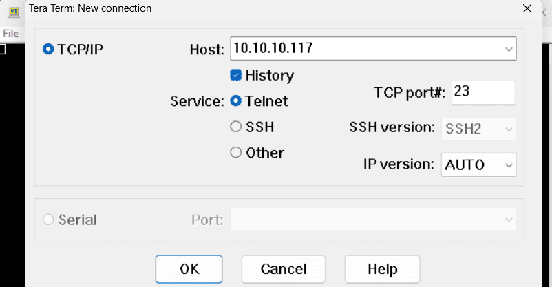
- Then select the terminal setup from the setup button and make sure the settings are as shown below, and press OK.
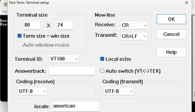
-
- Type the User name and Password when asked.
- Press ENTER key and the command prompt should appear. Commands listed in the table in section “Sending Commands” can be entered here now. For example, here is the response for “ver” command.
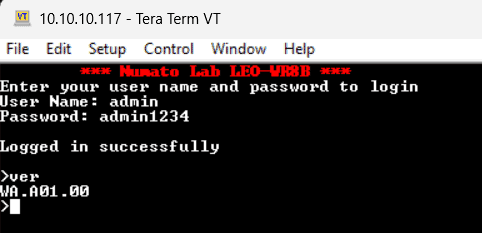
Get started with application commands by referring to the Sending commands.
Controlling through REST API commands
This module supports REST API commands.
Refer to the ‘REST API Command Set‘ knowledge base to know more.
Below is the example image related to controlling these modules through REST API commands.
Configuration Command Set
Device configuration
| No. | Command | Parameters | Example | Description |
|---|---|---|---|---|
| Device Configuration | ||||
| 1 | ver | none | ver | Returns firmware Version |
| 2 | info | none | info | Display information about the module including Failsafe and Power-on status |
| 3 | id | get/set xxxxxxxx | id get, id set 12345678 | Reads/Sets id of the module |
| 4 | usr | get/set xxxxxxxx | usr get, usr set admin | Reads/Sets User name |
| 5 | pass | get/set xxxxxxxx | pass get, pass set admin1234 | Reads/Sets Password |
| 6 | usr auth | get/on/off | usr auth get, usr auth on, usr auth off | Returns User Auth status, Enable/Disable Authentication |
| 7 | access | ip get/on/off/set N xxx.xxx.xxx.xxx | access ip get | Read the stored IP in the memory. |
| access ip on/off | Enable or disabling the IP based access to the module, this command adds filtering. Once the command is enabled, the stored IP using the access ip set command will be able to access the module. By default access IP is disabled. | |||
| access ip set N xxx.xxx.xxx.xxx | Set the acceptable IP in the network and save the same. Where N is the number 0-9, maximum 10 IP we can store in the non-volatile memory. Eg: access ip set 0 192.168.0. 2 |
|||
| 8 | reboot | none | reboot | Reboot does a soft-reset. |
| 9 | app mode | none | app mode | Exit the configuration interface and enter to the application mode and start the application communications. |
| 10 | fact reset | none | fact reset | Perform device factory reset |
Network0 (Ethernet) Configuration
| No. | Command | Parameters | Example | Description |
|---|---|---|---|---|
| Network0 Configuration | ||||
| 1 | net0 | mac get | net0 mac get | Read the MAC id of the NET0 Ethernet Interface. |
| 2 | hostname get | net0 hostname get | Shows the hostname of the Ethernet interface | |
| 3 | hostname set xxxxxxxxxxxxxxx | net0 hostname set numato-eth | Sets the hostname to the Ethernet Interface. Hostname length must be between 1 and 15 characters, and only the '-' symbol is allowed |
|
| 4 | dhcp get | net0 dhcp get | Shows the DHCP status of the Ethernet Interface | |
| 5 | dhcp on/off | net0 dhcp on/off | Enable or disable the DHCP of the Ethernet Interface | |
| 6 | ip get | net0 ip get | Read the status of DHCP and the static IP of the Ethernet Interface. If DHCP is enabled it will display the DHCP status, and if it is disabled it will display the static IP too | |
| 7 | ip set xxx.xxx.xxx.xxx | net0 ip set 192.168.5.36 | Sets the static IP to the Ethernet Interface. | |
| 8 | sm get | net0 sm get | Read the Subnet Mask of the Ethernet Interface. If DHCP is enabled it will display the DHCP status and if it is disabled it will display the Subnet Mask value. | |
| 9 | sm set xxx.xxx.xxx.xxx | net0 sm set 255.255.255.0 | Sets the Subnet Mask to the Ethernet Interface. | |
| 10 | gw get | net0 gw get | Reads the Gateway of the Ethernet Interface. If DHCP is enabled it will display the DHCP status and if it is disabled it will display the Gateway value. | |
| 11 | gw set xxx.xxx.xxx.xxx | net0 gw set 192.168.5.1 | Sets the gateway to the Ethernet Interface. | |
| Telnet Configuration | ||||
| 12 | telnet auth get | net0 telnet auth get | Read the status of telnet authentication. | |
| 13 | telnet auth on/off | net0 telnet auth on/off | Enable and disable the telnet authentication. telnet auth on enabling the telnet authentication and telnet off disabling the telnet authentication. |
|
| 14 | telnet port get | net0 telnet port get | Shows the telnet port. | |
| 15 | telnet port set xxxxx | net0 telnet port set xxxxx | Sets the telnet port, where xxxxx can be in the range of 1 to 65535. The default value of the telnet port is 23. |
|
Network1 (Wi-Fi) Configuration
| No. | Command | Parameters | Example | Description |
|---|---|---|---|---|
| Network1 Configuration | ||||
| 1 | net1 | mac get | net1 mac get | Read the MAC id of the NET1 Wi-Fi Interface. |
| 2 | hostname get | net1 hostname get | Shows the hostname of the Wi-Fi interface | |
| 3 | hostname set xxxxxxxxxxxxxxx | net1 hostname set Numato123 | Set a unique hostname for the device. This is useful for identifying the device on the network and can be customized to reflect the device’s role or location. Hostname length must be between 1 and 15 characters, and only the '-' symbol is allowed |
|
| 4 | ssid get | net1 ssid get | Shows the SSID of the configured Wi-Fi network | |
| 5 | ssid set xxxxxxxx | net1 ssid set admin | Enter the SSID (network name) of the Wi-Fi network that the device should connect to. This is the name of the wireless network that the device will search for and connect to. SSID length must be between 1 and 31 characters and '\', '/', space symbols are restricted |
|
| 6 | pass get | net1 pass get | Shows the password of the configured Wi-Fi network | |
| 7 | pass set xxxxxxxx | net1 pass set admin1234 | Enter the Wi-Fi password for the SSID you've selected. This ensures secure communication between the device and your network. Password length must be between 1 and 31 characters and '\', '/', space symbols are restricted |
|
| 8 | dhcp get | net1 dhcp get | Shows the DHCP status of the Wi-Fi Interface | |
| 9 | dhcp on/off | net1 dhcp on/off | Enable or disable the DHCP of the Wi-Fi Interface | |
| 10 | ip get | net1 ip get | Read the status of DHCP and the static IP of the Wi-Fi Interface. If DHCP is enabled it will display the DHCP status and if it is disabled it will display the static IP too | |
| 11 | ip set xxx.xxx.xxx.xxx | net1 ip set 192.168.5.48 | Sets the static IP to the Wi-Fi Interface. |
|
| 12 | sm get | net1 sm get | Read the Subnet Mask of the Wi-Fi Interface. If DHCP is enabled it will display the DHCP status and if it is disabled it will display the Subnet Mask value. | |
| 13 | sm set xxx.xxx.xxx.xxx | net1 sm set 255.255.255.0 | Sets the Subnet Mask to the Wi-Fi Interface. |
|
| 14 | gw get | net1 gw get | Reads the Gateway of the Wi-Fi Interface. If DHCP is enabled it will display the DHCP status and if it is disabled it will display the Gateway value. | |
| 15 | gw set xxx.xxx.xxx.xxx | net1 gw set 192.168.5.1 | Sets the gateway to the Wi-Fi Interface. | |
| 16 | pdns get | net1 pdns get | Reads the Primary DNS of the Wi-Fi Interface. If DHCP is enabled it will display the DHCP status and if it is disabled it will display the Primary DNS value. | |
| 17 | pdns set xxx.xxx.xxx.xxx | net1 pdns set 8.8.8.8 | Sets the primary dns to the Wi-Fi Interface. |
|
Sending Commands
One of the most powerful features of this module is the simple easy to use command set it supports. This command set allows for a very simple interface to access the features of the module through TELNET protocol. The following sections give details of the command set and how to use the command set.
The command set
This product supports a very simple command set that is designed to be less cryptic and easy to use manually (using terminal emulation programs that support TELNET) or through a program written in one of the many supported languages
List of currently supported commands.
| No. | Command | Parameters | Example | Description |
|---|---|---|---|---|
| 1 | ver | None | ver | Returns firmware Version |
| 2 | id | get/set xxxxxxxx | id get, id set 12345678 | Reads/Sets id of the module |
| 3 | usr | get/set xxxxxxxx | usr get, usr set admin | Reads/Sets User name |
| 4 | pass | get/set xxxxxxxxx | pass get, pass set admin1234 | Reads/Sets Password |
| 5 | usr auth | get/on/off | usr auth get, usr auth on, usr auth off | Returns User Auth status, Enable/Disable Authentication |
| 6 | relay | on/off/status [relay number]/status/on all/off all/ write [relay_group] [relay_map]/ pwron [relay_group] [relay_map]/get/disable/ tmr get [relay_number]/ get/disable/disable [relay_number]/[relay_number] [mode] [delay_seconds] | relay on 000, relay off 000, relay status 000, relay status, relay on all, relay off all, relay write A 00ff, relay pwron A 00ff, relay pwron get, relay pwron disable, relay tmr get 000, relay tmr get, relay tmr disable, relay tmr disable 000, relay tmr 000 M0 2 | Relay Control |
| 7 | gpi | gpi read [input number], gpi notify on/off/get | gpi read 000, gpi read, gpi notify on, gpi notify off. gpi notify get | Monitor General Purpose Input |
| 8 | smart | get/-i/-r/disable/ [input] [mode] [target_output] [value] | smart get 000, smart -i 000, smart -r 000, smart disable, smart 000 L 000 1 | Read configured data, clear configured input, clear configured relay, disable entire smart action feature, configure smart feature |
| 9 | fs | get input_number/reset/disable/ [input] [mode] [relay_group] [relay_map] | fs get 000, fs reset, fs disable, fs 000 L A 0012 | Read status of IO failsafe, Manual Reset Failsafe, Disable Failsafe, Configure Failsafe |
| 10 | info | none | info | Display information about the module including Smart Action and Power-on status |
| 11 | reboot | none | reboot | Power reset does a soft-reset. |
| 12 | config mode | none | config mode | Exit the application mode and enter to the configuration interface and start the configuration via USB. |
| 13 | fact | reset | fact reset | Perform device factory reset Configure the module to factory default. |
The tables below provide more detailed information about available commands.
Device Command Set
| No. | Command | Example | Description |
|---|---|---|---|
| 1 | ver | ver | This command returns the current firmware version of the device. Command Format verResponse Format xxxxxxxx – Firmware version string Description Returns the firmware version currently running on the device. Example ver Returns firmware version Notes The version format may vary depending on the firmware release. |
| 2 | id | id get id set xxxxxxxx | This command is used to read and configure the device ID. Command Format id get id set xx – New device ID (exactly 8 characters) Description id get returns the current device ID. id set x updates the device ID to the specified value.Example id get Returns the current device ID id set DEV12345 Sets the device ID to "DEV12345"Notes The device ID must be exactly 8 characters in length. Changing the device ID may affect identification in connected systems or applications.n a new ID to the module. “x” stands for alphanumeric characters including symbols. The new ID must be exactly 8 characters in length. |
| 3 | usr | usr get usr set xxxxxxxx | This command is used to read and configure the device username. Command Format usr get usr set xx – New username (1 to 8 characters) Description usr get returns the current username configured on the device. usr set x updates the username to the specified value.Example usr get Returns the current username usr set admin Sets the username to "admin"Notes Username length must be between 1 and 8 characters. Changing the username affects authentication over the USB interface. |
| 4 | pass | pass get pass set xxxxxxxxx | This command is used to read and configure the device password. Command Format pass get pass set xx – New password (9 to 31 characters, alphanumeric and symbols supported are !, @, ^, (, ))Description pass get returns the current password configured on the device. pass set x updates the device password to the specified value.Example pass get Returns the current password pass set admin1234 Sets the password to "admin1234"Notes Password length must be between 9 and 31 characters. Use a strong password to ensure secure access to the device. Changing the password affects authentication over the USB interface. |
| 5 | usr auth | usr auth get | This command returns the current USB authentication status. Command Format usr auth getResponse Format USR Authentication Disabled – Authentication is DISABLED USR Authentication Enabled– Authentication is ENABLED Description Returns whether USB authentication is currently enabled or disabled. Example usr auth get Returns USR Authentication Enabled if authentication is enabled, otherwise USR Authentication DisabledNotes Ensure authentication is enabled for secure operation. When disabled, commands can be executed without credentials. |
| usr auth on | This command enables USB authentication for the device. Command Format usr auth onDescription Enables authentication over the USB interface. Once enabled, valid credentials are required to execute commands. Example usr auth on Enables USB authenticationNotes Ensure valid username and password are configured before enabling authentication. If credentials are unknown, use factory reset to restore default access. |
||
| usr auth off | This command disables USB authentication for the device. Command Format usr auth offDescription Disables authentication over the USB interface. Once disabled, commands can be executed without requiring a username or password. Example usr auth off Disables USB authenticationNotes Disabling authentication reduces access security. It is recommended to use this feature only in trusted environments. |
||
| 6 | info | info | This command displays module information, including Smart Action status, Power-on configuration, and IO Failsafe status. Command Format infoDescription Returns a summary of key module configurations in a single response. Helps in quickly verifying system setup and operational status. Example info Returns module configuration summaryNotes The response format may vary based on firmware version. Use individual commands for detailed configuration of each feature. |
| 7 | config mode | config mode | This command exits the application interface and enter to the configuration mode. Command Format config modeDescription The device restarts the configuration mode without altering any stored configuration. Example config mode Enters configuration mode |
| 8 | reboot | reboot | This command performs a soft reset of the device. Command Format rebootDescription Restarts the device without altering any stored configuration. All settings, including Smart Action, Timer, Failsafe, and credentials, remain unchanged. Example reboot Performs a device soft resetNotes The device will briefly disconnect and restart after execution. Use this command to recover from temporary issues or apply configuration changes. |
| 9 | fact reset | fact reset | This command performs a factory reset of the device. Command Format fact resetDescription Restores the device to factory default settings. All configurations, including Smart Action, Timer, Failsafe, credentials, and other user-defined parameters, will be erased. Example fact reset Performs a device factory resetNotes The device will briefly disconnect, the LED will blink during the reset process, and the device will restart upon completion. Use this command to recover the device or reset all configurations. This action cannot be undone. |
Relay Command Set
| No. | Command | Example | Description |
|---|---|---|---|
| 1 | relay | relay on xxx | This command turns ON a specific relay channel. Command Format relay on xxxxxx – Relay number (Range: 000 to 007, numbering starts from 0) Description Turns ON the selected relay channel. Example relay on 000 Turns ON Relay 0Notes Ensure the relay number is within the valid range (000–007). The command immediately updates the relay state. If a relay is mapped to smart action or relay timer, manual control will be restricted |
| 2 | relay off xxx | This command turns OFF a specific relay channel. Command Format relay off xxxxxx – Relay number (Range: 000 to 007, numbering starts from 0) Description Turns OFF the selected relay channel. Example relay off 000 Turns OFF Relay 0Notes Ensure the relay number is within the valid range (000–007). The command immediately updates the relay state. If a relay is mapped to smart action or relay timer, manual control will be restricted |
|
| 3 | relay status xxx | This command returns the current status of a specific relay channel. Command Format relay status xxxxxx – Relay number (Range: 000 to 007, numbering starts from 0) Response Format on or offon – Relay is ON off – Relay is OFF Description Returns the current state of the selected relay channel. Example relay status 000 Returns status of Relay 0Notes Ensure the relay number is within the valid range (000–007). The response reflects the real-time state of the relay at the moment of execution. |
|
| 4 | relay status | This command reads the current status of all relays in a single operation. Command Format relay statusResponse Format A:XXXXXXXX – Current relay state (hexadecimal value) Description The returned value represents the state of all relays in the selected group. Each bit corresponds to one relay channel. 0 – Relay OFF 1 – Relay ON Example A:0000 – All relays are OFF A:00FF – All relays are ON Group Representation A – Group A (first 16 relays. ) Each bit represents one relay channel. Value Range WR8: 0000 to 00FF (8-bit) WR16: 0000 to FFFF (16-bit) |
|
| 5 | relay on all | This command turns ON all relay channels. Command Format relay on allDescription Turns ON all relays in a single operation, regardless of their current state. Example relay on all Turns ON all relaysNotes This command immediately sets all relay outputs to ON. It overrides any previously set relay states. If a relay is mapped to smart action or relay timer, manual control will be restricted |
|
| 6 | relay off all | This command turns OFF all relay channels. Command Format relay off allDescription Turns OFF all relays in a single operation, regardless of their current state. Example relay off all Turns OFF all relaysNotes This command immediately sets all relay outputs to OFF. It overrides any previously set relay states. If a relay is mapped to smart action or relay timer, manual control will be restricted |
|
| 7 | relay write A 00xx | This command controls all relays in a single operation using a hexadecimal value. Command Format relay write G xxxxG – Relay group identifier A – Group A (relays 0 to 15) xxxx – Relay state value (hexadecimal) Description Sets the state of multiple relays simultaneously. Each bit in the hexadecimal value represents one relay in the group. Bit Representation 0 – Relay OFF 1 – Relay ON Example relay write A 00FF – Turns ON all relays in Group AValue Range WR8: 0000 to 00FF (8-bit) WR16: 0000 to FFFF (16-bit)Notes Each bit position corresponds to a relay channel within the group. Ensure correct bit mapping to avoid unintended relay switching. If a relay is mapped to smart action or relay timer, manual control will be restricted |
|
| 8 | relay pwron A 00xx | This command sets the relay power-on state for the module. Command Format relay pwron G xxxxG – Relay group identifier A – Group A (first 16 relays) xxxx – Relay state value (hexadecimal) Description Defines the relay states that will be applied when the device powers on or resets. Each bit in the hexadecimal value represents the state of a relay. Bit Representation 0 – Relay OFF 1 – Relay ON Example relay pwron A 0003 0000 0000 0000 0011 → Relays 0 and 1 ON, all others OFF Value Range WR8: 0000 to 00FF (8-bit) WR16: 0000 to FFFF (16-bit)Notes The configured state is applied on device power-up or reset. Ensure correct bit mapping to avoid unintended relay activation. If a relay is mapped to smart action or relay timer, manual control will be restricted |
|
| relay pwron get | This command reads the power-on status of all relays in a single operation. Command Format relay pwron getResponse Format A:XXXXXXXX – Power-On values of the relays (hexadecimal value) Description The returned value represents the state of all relays in the selected group. Each bit corresponds to one relay channel. 0 – Relay OFF 1 – Relay ON Example A:0000 – All relays are OFF A:00FF – All relays are ON Group Representation A – Group A (first 16 relays) Each bit represents one relay channel Value Range WR8: 0000 to 00FF (8-bit) WR16: 0000 to FFFF (16-bit) |
||
| relay pwron disable | This command disables the Relay Power-On feature for all relay channels. Command Format relay pwron disableDescription Disables power-on feature to all relays. Once disabled, no relay will operate based on power-on settings. Example relay pwron disable Disables power-on feature to all relaysNotes Use the power-on command to re-enable power-on based behavior. |
||
| Relay Timer Commands | |||
| 9 | relay tmr get xxx | This command returns the current configuration and status of a specific relay timer. Command Format relay tmr get xxxxxx – Relay number (Range: 000 to 007, numbering starts from 0) Response Format Mx D:yyyyM:Mx – Timer mode (M0 [Delayed ON], M1 [Delayed OFF], M2 [Toggle]) D:yyyy – Delay value in seconds Description Returns the timer configuration for the selected relay. Includes the configured timer mode and delay value. Example relay tmr get 000 Returns timer status for Relay 0Notes Ensure the relay number is within the valid range (000–007). If no timer is configured and the M0 or M1 delay expires, the response will indicate “timer not active” |
|
| 10 | relay tmr get | This command returns the list of relays with timer configurations. Command Format relay tmr getResponse Format xxx xxx xxxxxx – Relay numbers with timer configured Description Returns a list of relay channels for which timer functionality is currently configured. Only relays with active timer settings are included in the response. Example relay tmr get 000 002 005 Indicates that relay timers are configured on Relay 0, 2, and 5. Notes If no relay timers are configured, the response may indicate an empty or default state. Use relay tmr get xxx for detailed timer configuration of a specific relay. |
|
| 11 | relay tmr disable xxx | This command disables the relay timer configuration for the specified relay channel. Command Format relay tmr disable xxxxxx – Relay number (Range: 000 to 007) Description Disables the timer configured for the selected relay. Once disabled, the relay will no longer operate based on timer settings. Example relay tmr disable 000 Disables timer for Relay 0Notes Ensure the relay number is within the valid range (000–007). |
|
| 12 | relay tmr disable | This command disables the Relay Timer feature for all relay channels. Command Format relay tmr disableDescription Disables all configured relay timers. Once disabled, no relay will operate based on timer settings. Example relay tmr disable Disables all relay timer operationsNotes Use the timer configuration command to re-enable timer-based behavior. |
|
| 13 | relay tmr [relay_number] [timer_mode] [timer_delay] | This command configures the timer behavior of a specific relay channel, enabling precise control over relay operation based on time. Command Format relay tmr xxx mode delayxxx – Relay number (Range: 000 to 007) mode – Defines the operating mode of the relay timer M0 – Delayed ON M1 – Delayed OFF M2 – Toggle Timer delay – Time delay in seconds (Range: 1 to 3600 seconds) Description Configures time-based behavior for the selected relay channel. The relay action depends on the selected mode and delay value. Examples relay tmr 000 M0 1 – Turns ON Relay 0 after a delay of 1 second relay tmr 000 M1 4 – Turns OFF Relay 0 after a delay of 4 seconds relay tmr 000 M2 10 – Toggles Relay 0 every 10 seconds Notes Timer configurations are persistent and remain active even after a power reset. A configured timer continues to operate until it is explicitly disabled or the device is factory reset. If a relay is already mapped to smart action, relay timer cannot be configured If the relay timer mode is set to M0 or M1, the relay becomes available for manual control after the specified delay |
|
GPI Command Set
| No. | Command | Example | Description |
|---|---|---|---|
| 1 | gpi | gpi read xxx | This command reads the current state of a specific digital input (GPI). Command Format gpi read xxx xxx – Digital input number (Range: 000 to 007) Response Format 0 or 1 0 – Input is LOW 1 – Input is HIGH Description The command returns the instantaneous logic level of the selected digital input. Example gpi read 000 Returns 0 or 1 depending on the current state of GPI 0 Notes Ensure the input number is within the valid range (000–007). The response reflects the real-time state of the input at the moment of execution. |
| 2 | gpi read | This command reads the current status of all digital inputs in a single operation and returns the values grouped by input channels. Command Format gpi readResponse Format A:XXXXXXXX – Current digital input state (hexadecimal value) Description The returned value represents the state of all digital inputs in the selected group. Each bit corresponds to one input channel. 0 – GPI LOW 1 – GPI HIGH Example A:00FF – All inputs in Group A are HIGH A:0001 – GPI 0 is HIGH, all other inputs are LOW Group Representation A – Group A (first 16 digital inputs) Each bit represents one input channel 0 – GPI LOW 1 – GPI HIGH Value Range 0000 to 00FF (8-bit) |
|
| 3 | gpi notify on | This command enables digital input (GPI) change notifications. When enabled, the device monitors input state changes and sends a notification to the host whenever a change is detected. Command Format gpi notify onNotification Format A:XXXX/YYYYXXXX – Current input state YYYY – Previous input state Description A notification is sent only when a change is detected in any input bit. The value represents the state of all inputs in the group using hexadecimal format. Example A:00FE/00FF Previous state: 00FF Current state: 00FE This indicates that GPI 0 changed from HIGH (1) to LOW (0), triggering the notification. Group Representation A – Group A (first 16 digital inputs) Each bit represents one input channel 0 – GPI LOW 1 – GPI HIGH Value Range 0000 to 00FF (8-bit) |
|
| 4 | gpi notify off | This command disables the GPI change notification feature. Command Format gpi notify offResponse Format Gpi Notify DisabledDescription Disables automatic notifications for digital input state changes. Once disabled, the device will no longer send updates to the host when input states change. Example gpi notify off Disables GPI change notifications |
|
| 5 | gpi notify get | This command returns whether the GPI change notification feature is enabled or disabled. Command Format gpi notify getResponse Format Gpi Notify Enabled or Gpi Notify DisabledDescription Returns the current status of the gpi change notification feature. Example gpi notify get Returns Gpi Notify Enabled or Gpi Notify Disabled |
Standalone Commands
Standalone commands are supported in both USB Configuration Mode and Telnet Application Mode, providing flexibility in configuring and managing the device through either interface. These commands include the Smart Action Engine and IO Fail-safe Control commands, which allow users to configure automation actions and manage fail-safe behaviour effectively.
Smart Action Engine Configuration
| No. | Command | Parameters | Example | Description |
|---|---|---|---|---|
| 1 | smart | get xxx/ get/ -i xxx/ -r xxx/disable/ [input] [mode] [target_output] [value] | smart get 000, smart -i 000, smart -r 000, smart disable, smart 000 L 000 1 | Read configured data, clear configured input, clear configured relay, disable entire smart action feature, configure smart feature |
| Smart Action Engine Detailed Commands | ||||
| 1 | smart | get xxx | smart get 000 | This command returns the current Smart Action configuration for a specific digital input channel. Command Format smart get xxxxxx – Digital input number (Range: 000 to 007) Response Format M:L R:000:HM – Input mode (L: LOW, H: HIGH, F: FOLLOW) R – Relay number H / L – Trigger value (HIGH / LOW) Description Returns the Smart Action settings configured for the selected digital input Includes operating mode, mapped relay outputs, and configured trigger values Example smart get 000 Returns Smart Action configuration for Digital Input (GPI) 0Notes
|
| 2 | get | smart get | This command returns the list of digital inputs that have Smart Action configured. Command Format smart getResponse Format Mapped IOs: xxx xxx xxxxxx – Digital input numbers with Smart Action configured Description Returns a list of digital input channels for which Smart Action is currently configured. Only mapped inputs are included in the response. Example smart get Mapped IOs: 000 001 007 Indicates that Smart Action is configured on Digital Inputs 0, 1, and 7. Notes If no Smart Action is configured, the response may indicate an empty or default state. Use smart get xxx for detailed configuration of a specific input. |
|
| 3 | -i xxx | smart -i 000 | This command disables the configured digital input for the specified channel. Command Format smart -i xxxxxx – Digital input number (Range: 000 to 007) Description Disables the selected digital input channel. Example smart -i 000 Disables Smart action mapped on digital Input (GPI) 0Notes Ensure the input number is within the valid range (000–007). |
|
| 4 | -r xxx | smart -r 000 | This command disables the configured relay for the specified channel. Command Format smart -r xxxxxx – Relay number (Range: 000 to 007) Description Disables the selected relay channel mapped to smart action. Example smart -r 000 Disables Relay 0 mapped to smart actionNotes Ensure the relay number is within the valid range (000–007). |
|
| 5 | disable | smart disable | This command disables the Smart Action feature for all input channels. Command Format smart disableDescription Disables all configured Smart Actions. Once disabled, no digital input will trigger any relay output based on Smart Action logic. Example smart disable Disables Smart Action feature for all inputs |
|
| 6 | smart [input] [mode] [target_output] [value] | smart 000 L 000 1 | This command configures the Smart Action feature. Smart Action maps digital inputs to relay outputs and automates relay control based on input state. Command Format smart xxx mode target_output valuexxx – Digital input number (Range: 000 to 007) mode – Defines the trigger condition for the relay L – Trigger when input is LOW H – Trigger when input is HIGH F – Follow mode (relay follows input state) target_output – Relay to be controlled by the selected digital input (Range: 000 to 007) value – Relay output state when triggered 0 – Relay OFF 1 – Relay ON Not required in F (Follow) mode Description Each command links a digital input (same index as xxx) to a relay output. The relay action depends on the selected mode and trigger condition. Examples smart 000 L 000 1 – When digital input 0 goes LOW, Relay 0 turns ON smart 001 H 002 0 – When digital input 1 goes HIGH, Relay 2 turns OFF smart 003 F 003 – Relay 3 follows digital input 3 (LOW - OFF, HIGH - ON)Notes Digital input index corresponds to the input used in the command. Follow mode (F) continuously mirrors input state without delay. If a relay is mapped to relay timer, the same relay cannot be configured with smart action feature One relay can be mapped to only one input, One input can have multiple relays mapped to it |
|
IO Failsafe Control Configuration
| No. | Command | Parameters | Example | Description |
|---|---|---|---|---|
| 1 | fs | get/reset/disable/ [input] [mode] [relay_group] [relay_map] | fs get, fs reset, fs disable, fs 000 L A 0012 | Read status of IO failsafe, Manual Reset Failsafe, Disable Failsafe, Configure Failsafe |
| IO Failsafe Control Detailed Commands | ||||
| 1 | fs | get | fs get | This command returns the IO Failsafe configuration for the specified digital input. Command Format fs getResponse Format I:xxx M:X G:X V:xxxxI:xxx – Digital input number M:X – Trigger mode (L: LOW, H: HIGH) G:X – Relay group (e.g., A) V:xxxx – Relay state value (hexadecimal) Description Returns the configured failsafe settings for the selected digital input. Includes trigger mode, relay group, and relay output value. Example fs get Returns failsafe configuration for Digital Input 0Notes If no failsafe is configured, the response will indicate "FS Not Configured". |
| 2 | reset | fs reset | This command performs a manual reset of the IO Failsafe condition to resume normal device operation. Command Format fs resetDescription Clears the active failsafe state triggered by a digital input. Restores normal operation of relay outputs and system behavior. Example fs reset Clears the failsafe condition and resumes operationNotes Use this command after resolving the condition that triggered the failsafe. If the trigger condition still exists, the failsafe may be reactivated immediately. |
|
| 3 | disable | fs disable | This command disables the IO Failsafe feature completely. Command Format fs disableDescription Disables all configured IO Failsafe behavior. Once disabled, digital inputs will no longer trigger failsafe actions. Example fs disable Disables IO Failsafe featureNotes Use the configuration command to reactivate failsafe behavior. |
|
| 4 | fs [input] [mode] [relay_group] [relay_value] | fs 000 L A 0012 | This command configures the IO Failsafe feature, enabling the module to automatically set relay states based on a defined digital input condition. Command Format fs xxx mode G xxxxxxx – Digital input number Note: The IO Failsafe feature currently supports Digital Input 0 only mode – Defines the trigger condition L – Trigger when input is LOW H – Trigger when input is HIGH G – Relay group identifier A – Group A (first 16 relays) xxxx – Relay state value (hexadecimal) Description Defines the relay output state when the specified digital input reaches the configured condition. Each bit in the hexadecimal value represents one relay. Bit Representation 0 – Relay OFF 1 – Relay ON Example Value 0003 – 0000 0000 0000 0011 Relays 0 and 1 ON, all others OFF Value Range WR8: 0000 to 00FF WR16: 0000 to FFFF Examples fs 000 L A 0012 When Digital Input 0 goes LOW, relays are set according to 0012 Relay 1 and Relay 4 turn ON, all others turn OFF fs 000 H A 0012 When Digital Input 0 goes HIGH, relays are set according to 0012 Relay 1 and Relay 4 turn ON, all others turn OFF |
|
Important Note: Once Fail-safe is triggered, relay control is disabled. Smart Action Engine rules, relay timers, and power-on commands are saved and will resume operation only after the Fail-safe condition is resolved.
Ethernet Web Interface
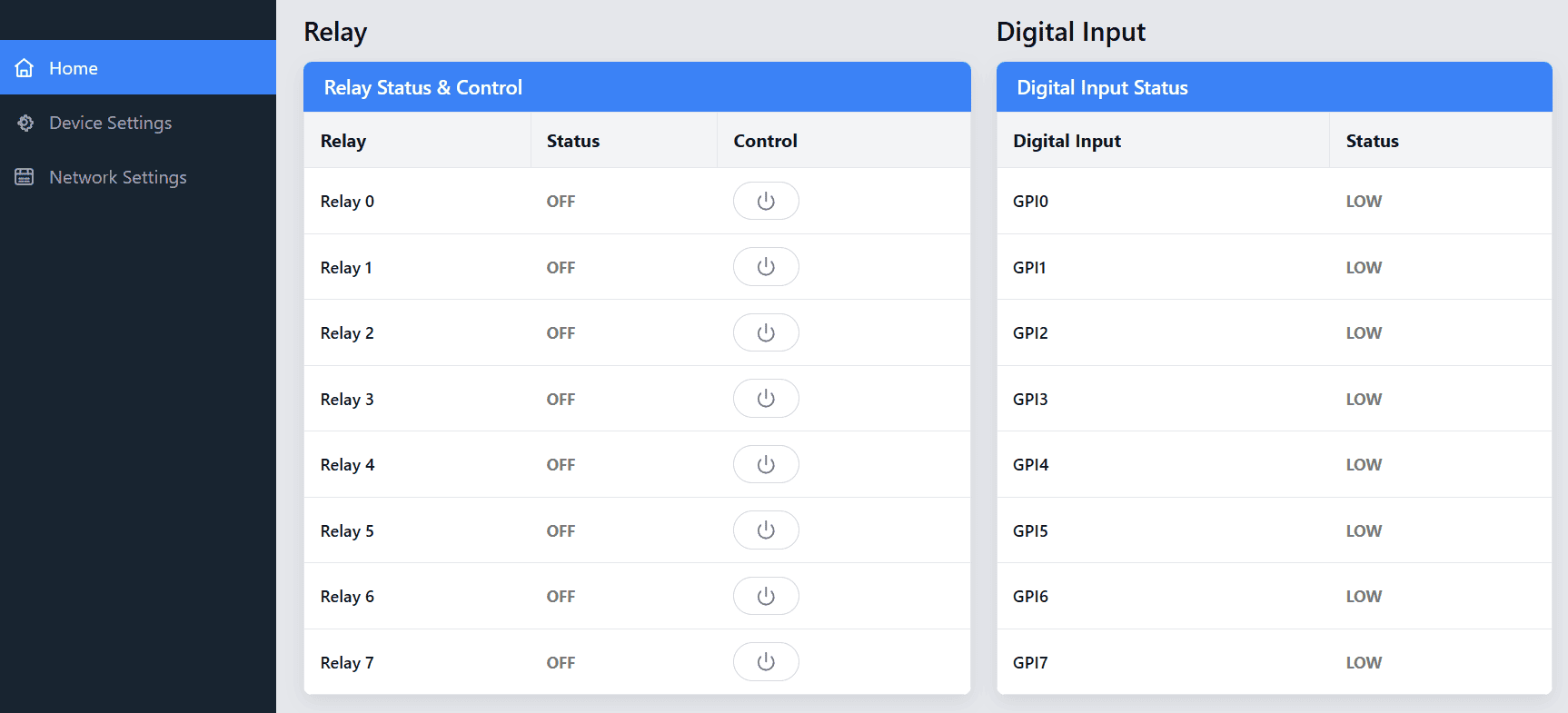
Through the Ethernet Web Interface, you can monitor and control GPIs and relays, as well as configure device settings and network settings.
GPI, Relay Status and Control
8 Relays on the board can be controlled over Ethernet. The Relay Index shows the corresponding relay on the board. Relays on the board can be turned on/off by clicking the Toggle Relay button next to the corresponding relay index. The status of the relays changes automatically for easy identification.
This board has 8 general-purpose high-voltage inputs. The status of the GPIs is shown on the home page.
Device Settings
Device Settings include Device Info, User Account, and Device Management.
Device Info
The Device Settings page shows the Device ID, firmware version, and serial number, and allows logged-in users to update and save the Device ID.
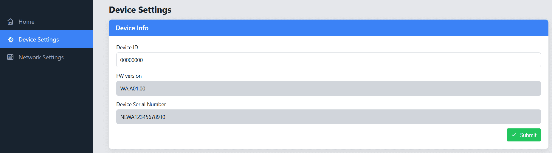
| Field | Description |
|---|---|
| Device ID | Displays and allows users to set the Device ID. |
| Firmware Version | Displays the current version of the firmware installed on your device. |
| Device Serial Number | The serial number specific to your device. This number is used for identification and support purposes. |
User Account
In the User Account section, you can manage your web login, including updating your Username and Password. This is important for keeping your account secure and ensuring only authorised users can access the device settings.
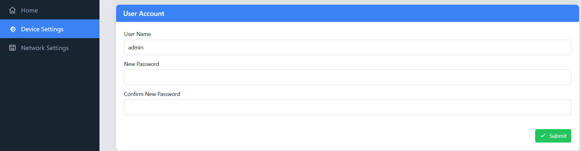
| Field | Description |
|---|---|
| Username | You can change your username by entering a new one in the provided field. Make sure to choose a unique and memorable username for easy access. |
| Password | Enter your new password here. Please follow the password strength requirements to ensure your password is strong and secure. |
| Confirm Password | Re-enter the new password here to confirm that both entries match. If they do not match, an error message will appear to help you correct it. |
Important Note: Your password will only be updated if both the New Password and Confirm Password fields match exactly. If they don’t match, a Warning message will display, and you will need to correct it before proceeding.
Important Update Information: Once you update the User Account Password, the web login password will be updated simultaneously. This means that the new password will be used for the web login to your device’s dashboard. Remember this new password for all future logins to your device.
Device Management
In the Device Management section, you can perform essential actions to manage your device, including rebooting the device and restoring it to its factory settings.



| Action | Description |
|---|---|
| Reboot | This option allows you to reset the device. Rebooting the device can be useful for applying new configurations and settings. |
| Config Mode | This option allows you to switch the device to USB Configuration mode |
| Factory Reset | This option restores the device to its original factory settings, erasing all user-configured settings and data. After a factory reset, the device will return to its default configuration. |
Important Note: Factory Reset is a permanent action. Once performed, all user-set data will be erased. This action cannot be undone.
Network Settings
The Ethernet Network Settings section allows you to configure the device’s wired network connection.
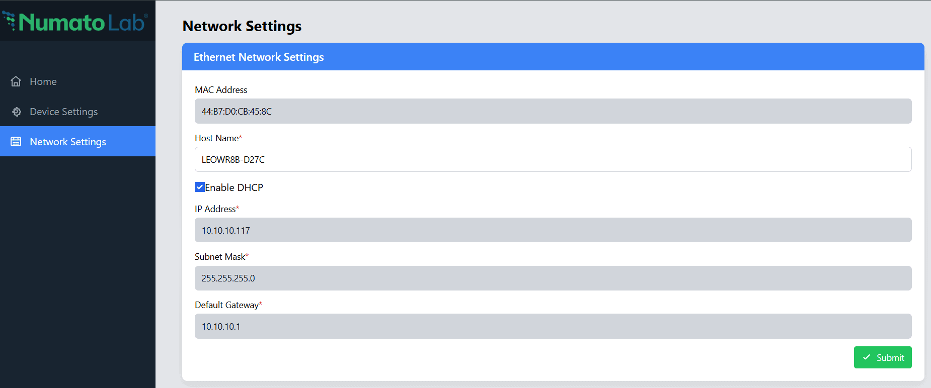
| Field | Description |
|---|---|
| MAC Address | Displays the unique MAC address assigned to the device. This address is used to identify the device on the network. |
| Host Name | Specifies the hostname of the device. The hostname can be customized to easily identify the device on the network. |
| Enable DHCP | When enabled, the device automatically obtains its IP address and other network parameters from a DHCP server. |
| IP Address | Displays or specifies the IP address assigned to the device. When DHCP is enabled, this address is assigned automatically. |
| Subnet Mask | Specifies the subnet mask used to determine the network address range. |
| Default Gateway | Specifies the gateway address used to communicate with devices outside the local network. |
After entering the required network parameters, click Submit to apply the settings.
Important Note: After you have saved all your settings in the device settings or/and network configurations, the changes will only take effect after the device is rebooted. You can reboot the device either:
- From the Webpage: Use the Reboot option in the device management section to apply all settings.
- From the Multi-Functionality Switch: Single-click reboots the device with the new configuration set.
After a reboot or a power reset, the module can be accessed via the DNS Hostname or the IP Address.
- Accessing via DNS Hostname:
- The device will be accessible via its DNS hostname. By default, the device will be configured with a device-specific unique hostname. The device can be accessed with the postfix “.local”, for example: hostname.local.
- Accessing via IP address:
-
If the device was configured with a static IP address, you can access it directly by entering the static IP address into your browser.
-
If the device was set to use dynamic IP (DHCP), you can either check the IP address assigned to the device through your router’s DHCP table or use a “arp -a” on command tool and check the IP assigned to your device MAC.
-
Wi-Fi Web Interface
Through the Wi-Fi Web Interface, you can monitor and control GPIs and relays, as well as configure Device Settings, Network Settings and MQTT Settings.
GPI, Relay Status and Control
8 Relays on the board can be controlled over Wi-Fi. The Relay Index shows the corresponding relay on the board. Relays on the board can be turned on/off by clicking the Toggle Relay button next to the corresponding relay index. The status of the relays changes automatically for easy identification.
This board has 8 general-purpose high-voltage inputs. The status of the GPIs is shown on the home page.
Device Settings
Device Settings include Device Info, User Account, NET1 OTA Firmware Update and Device Management.
Device Info
The Device Info section provides detailed information about your device. This section is read-only except for the Device ID, which can be edited and saved by logged-in users. You cannot modify the device information here except for the Device ID, but you can refer to it when needed.
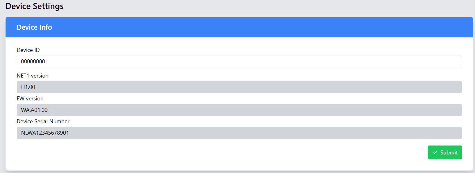
| Field | Description |
|---|---|
| Device ID | Displays Device ID. |
| Firmware Version | Displays the current version of the firmware installed on your device. |
| Device Serial Number | The serial number specific to your device. This number is used for identification and support purposes. |
These details are displayed in a simple, easy-to-read format.
User Account
In the User Account section, you can manage your web login, including updating your Username and Password. This is important for keeping your account secure and ensuring only authorized users can access the device settings.
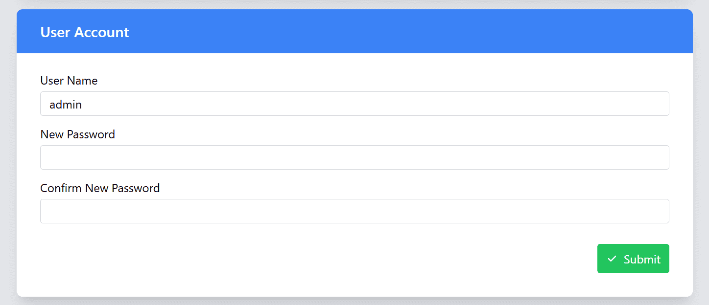
| Field | Description |
|---|---|
| Username | You can change your username by entering a new one in the provided field. Make sure to choose a unique and memorable username for easy access. |
| Password | Enter your new password here. Please follow the password strength requirements to ensure your password is strong and secure. |
| Confirm Password | Re-enter the new password here to confirm that both entries match. If they do not match, an error message will appear to help you correct it. |
Important Note: Your password will only be updated if both the New Password and Confirm Password fields match exactly. If there is a discrepancy, a Warning message will be displayed, and you will need to correct it before proceeding.
Important Update Information: Once you update the User Account Password, the web login password will be updated simultaneously. This means that the new password will be used for the web login to your device’s dashboard. Make sure to remember this new password for all future logins to your device.
NET1 OTA Firmware Update
The Firmware Update section allows you to keep your device up to date with the latest features, improvements, and bug fixes. Firmware updates can be performed only through the NET1 (Wi-Fi) interface.
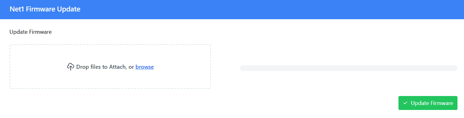
Important: Do not upload any unauthorized images via OTA. Doing so may permanently damage the device.
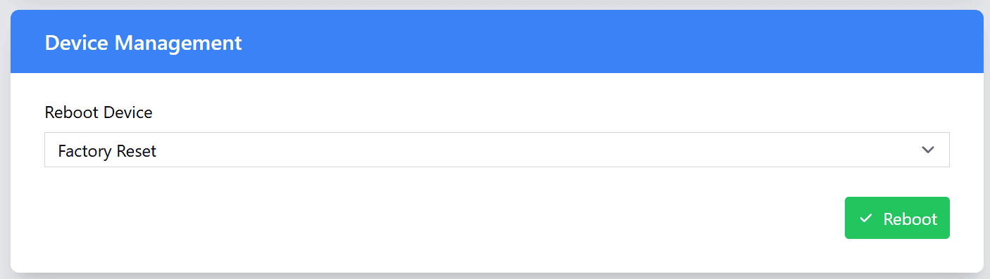
Device Management
In the Device Management section, you can perform essential actions to manage your device, including rebooting the device and restoring it to its factory settings.
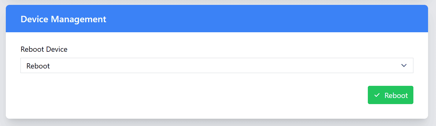

| Action | Description |
|---|---|
| Reboot | This option allows you to reset the device. Rebooting the device can be useful for applying new configurations and settings. |
| Config Mode | This option allows you to switch the device to USB Configuration mode |
| Factory Reset | This option restores the device to its original factory settings, erasing all user-configured settings and data. After a factory reset, the device will return to its default configuration. |
Important Note: Factory Reset is a permanent action. Once performed, all user-set data will be erased. This action cannot be undone.
Network Settings
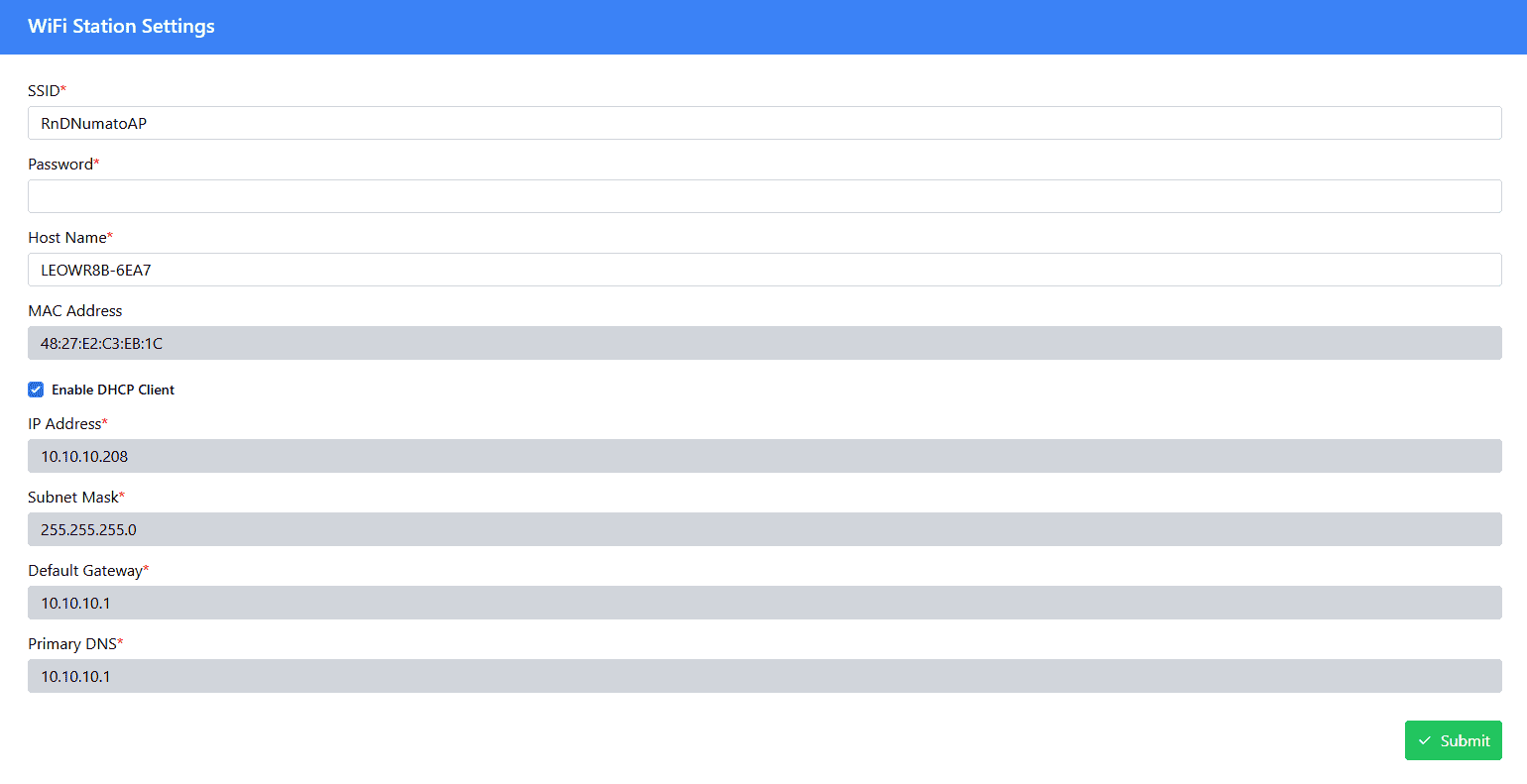
The Network Settings section allows the device to connect to an existing Wi-Fi network.
| Field | Description |
|---|---|
| SSID | Enter the name of the Wi-Fi network to which the device should connect. |
| Password | Enter the password for the selected Wi-Fi network. |
| Host Name | Specifies the hostname used to identify the device on the network. |
| MAC Address | Displays the MAC address of the Wi-Fi interface. |
| Enable DHCP Client | When enabled, the device automatically obtains its IP address and other network parameters from the network's DHCP server. |
| IP Address | Displays or specifies the IP address assigned to the Wi-Fi interface. |
| Subnet Mask | Specifies the subnet mask for the Wi-Fi network. |
| Default Gateway | Specifies the gateway address used for communication with other networks or the Internet. |
| Primary DNS | Specifies the primary DNS server used to resolve domain names into IP addresses. |
After entering the required network parameters, click Submit to apply the settings.
After a reboot or a power reset, the module can be accessed via the DNS Hostname or the IP Address.
- Accessing via DNS Hostname:
- The device will be accessible via its DNS hostname. By default, the device will be configured with a device specific unique hostname. The device can be accessed with the postfix “.local” example: hostname.local.
- Accessing via IP address:
-
If the device was configured with a static IP address, you can access it directly by entering the static IP address into your browser.
-
If the device was set to use dynamic IP (DHCP), you can either check the IP address assigned to the device through your router’s DHCP table or use a “arp -a” on command tool and check the IP assigned to your device MAC.
-
MQTT Settings
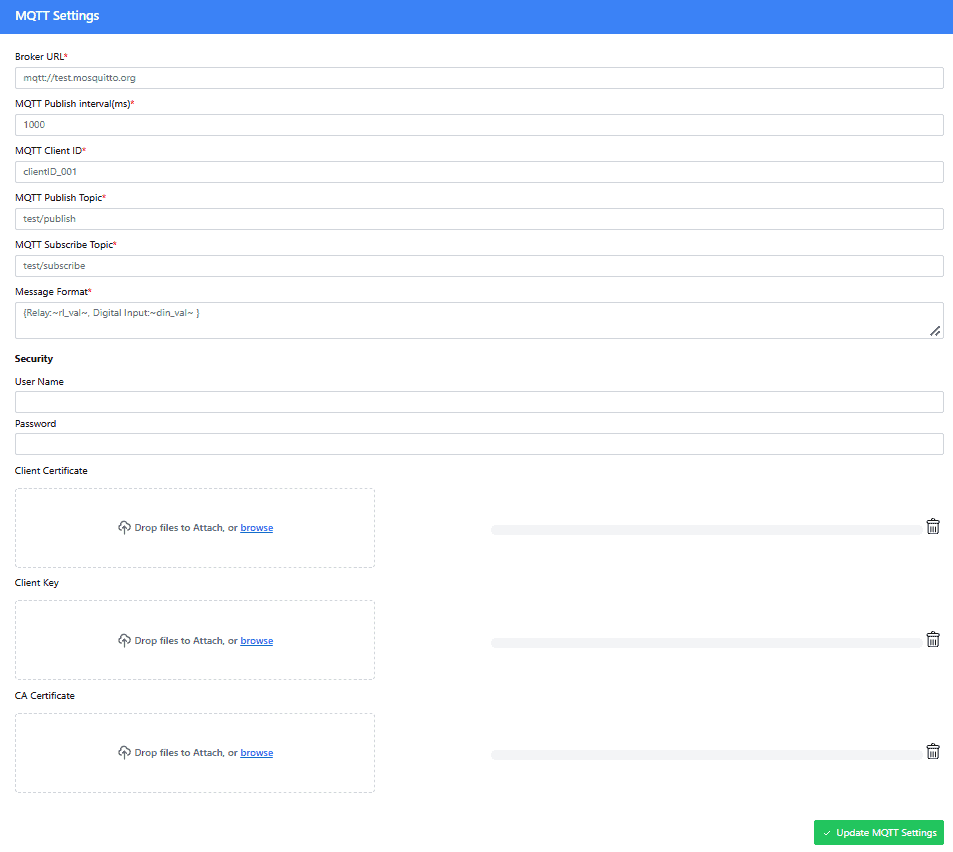
The MQTT/MQTTS Settings section allows you to configure the communication between your device and the MQTT broker. You can choose to use either MQTT (unencrypted) or MQTTS (secure, encrypted MQTT).
| Setting | Description | Mandatory for MQTT | Mandatory for MQTTS |
|---|---|---|---|
| Broker | Enter the MQTT broker address (IP or domain) with the appropriate protocol prefix (mqtt:// or mqtts://). For example, mqtt://broker.example.com or mqtts://broker.example.com. | YES | YES |
| Publish Interval (ms) | Set the publish interval in milliseconds. This defines how often the device will send data. | YES | YES |
| Client ID | Enter a unique Client ID for the device. This ID is used to identify the device on the MQTT broker. | YES | YES |
| Publish Topic | Define the topic for publishing data to the broker. Devices subscribing to this topic will receive the data. | YES | YES |
| Message Format | Specify the format of the message being sent to the broker. For example: 1. {Relay: ~rl_val~, Digital Input: ~din_val~}. The values ~rl_val~ and ~din_val~will be replaced by the actual Relay Status and Digital Input data from the device. 2.{"relay": 0,"State":1}. This message is used to control the relay number 0 with an ON state (1). | YES | YES |
| Username | Enter the Username for authentication if the MQTT broker requires security. | YES, If security is required. | YES, If security is required. |
| Password | Enter the Password for authentication if the MQTT broker requires security. | YES, If security is required. | YES, If security is required. |
| CA Certificate | Upload the CA certificate used to verify the broker’s identity. This is required for secure MQTT communication (MQTTS). | NO | YES |
| Client Certificate | Upload the client certificate used to authenticate the device to the broker in secure communication (MQTTS). | NO | YES |
| Client Key | Upload the client key associated with the client certificate for encrypted communication (MQTTS). | NO | YES |
Important Note: After you have saved all your settings in the device settings, network settings or/and MQTT settings, the changes will only take effect after the device is rebooted. You can reboot the device either:
- From the Webpage: Use the Reboot option in the device management section to apply all settings.
- From the Multi-Functionality Switch: Single-click reboots the device with the new configuration set.
Additional Information
Using GPI's with switches
It is possible to read the position of a switch that is connected to a GPI. A SPST or SPDT switch is recommended to use with GPI’s. Push switches do maintain the contacts closed only for a very short time so using them is 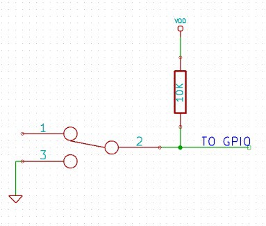 discouraged. The fundamental idea of using a switch with GPI is to have the switch cause a voltage level change at the GPI pin when pressed. Usually this is achieved by using an external pull-up resistor along with the switch. The pull up resistor is connected between the GPI and VDD and the switch is connected between the GPI and ground. When the switch is not pressed, the pull-up resistor will cause the GPI to stay at the VDD voltage level. When the switch is pressed, the GPI is short-circuited to ground and stays at zero voltage. This change in voltage, and thus the position of the switch, can be read using “gpi read” command. Please see the recommended connection diagram below
Using relay modules with inductive loads
It is important to take additional care when using relays with inductive loads. An inductive load is pretty much anything that has a coil and works based on magnetic principles like Motors, Solenoids and transformers. Inductive loads produce back emf when the magnitude of the load current changes. The back emf can be in the order of tens or even hundreds of voltage (See this Wikipedia article http://en.wikipedia.org/wiki/Counter-electromotive_force). This effect is most severe when power is disconnected from inductive load because the rate of change of current is maximum at that point. Even though the back emf lives only for a very short time (a few milliseconds) it can cause sparks between the relay contacts and can deteriorate the contact quality over time and reduce the life span for the relays considerably.
So it is important to take countermeasures to suppress the back emf to acceptable levels to protect relay contacts. 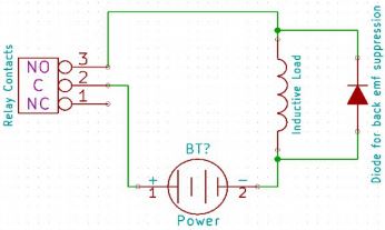 Usually this requires connecting electronic devices in parallel with the load such that they absorb the high voltage components generated by the load. For solenoids, connecting a diode (fast switching diode is recommended) in parallel to the load (in reverse direction to the load current) is very effective. A diode used for this purpose is usually called a freewheeling diode. Please see the diagram on the right for connection details.
A capacitor with proper rating is recommended for protecting the relay contacts when a motor is used as load. The capacitor should be rated enough to withstand the back emf that is generated by the motor. Please see the diagram below for connection details.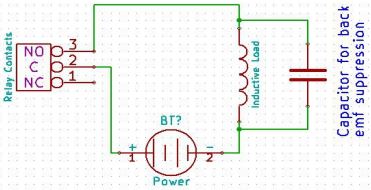
Please note that the relay modules are NOT shipped with back emf suppression devices pre-installed. The exact kind of suppression device and the parameters of the selected device can vary depending on the load itself. Some of the parameters that affects the suppression device selection are the inductance of the load, power supply voltage, load current, physical size/structure of the load etc.. It is obvious that it is impossible for us to predict these parameters and design required back emf suppression device and incorporate that on the board. So we believe this is a task best left to the module user. There is an excellent article on designing back emf suppression on Wikipedia at http://en.wikipedia.org/wiki/Flyback_diode
Mechanical Dimensions
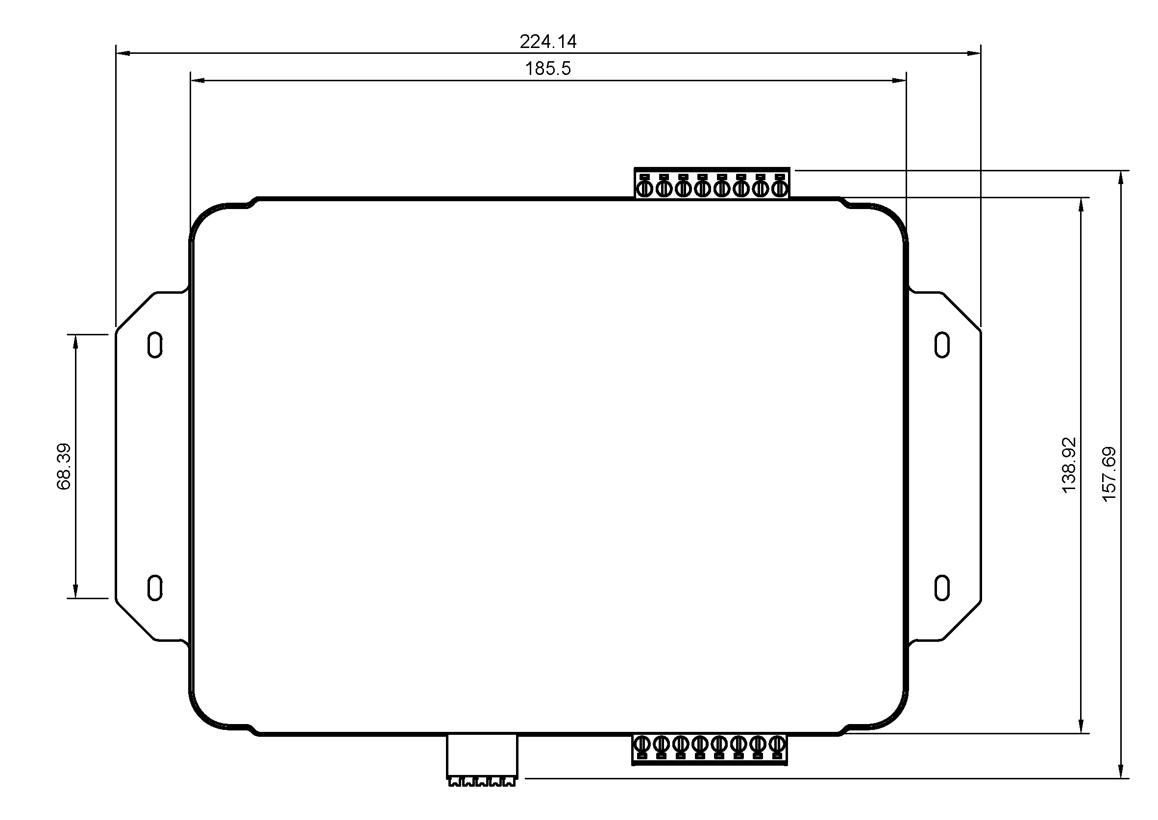
FAQ
Q. I need a customized version of this product, can Numato do the customization for me?
A. Yes, we can definitely do customization but there may be minimum order requirements depending on the level of customization required. Please write to sales@numato.com for a quote.
Q. Where can I buy this product?
A. All Numato products can be ordered directly from our web store http://www.numato.com. We accept major credit cards and Paypal and ship to almost all countries with a few exceptions. We do have distributors in many countries where you can place your order. Please find the current list of distributors here.