
Introduction
| SKU | Description | Operating temperature |
|---|---|---|
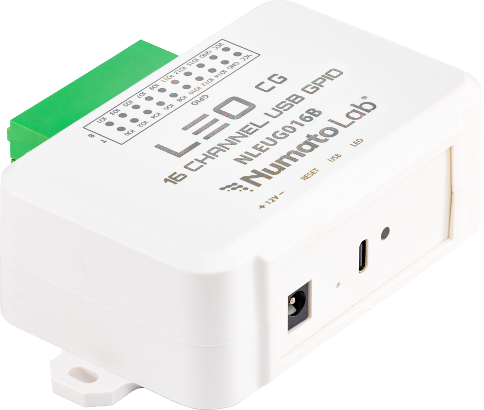
| NLEUG016B | LEO CG 16 Channel USB GPIO Module - CG16B | -40 ℃ to 85 ℃ |
Board Features
- 16 GPIOs – Supports 3.3V signals.
- 8 Analog Inputs multiplexed with the GPIOs
- 2 PWM channels multiplexed with the GPIOs
- USB Connectivity for convenient host-based control
- Human-Readable Command-Line Interface
- Smart Action Engine for rule-based automation and standalone operation
- Advanced GPIO Timer Functionality
- Configurable I/O Failsafe Engine
- DIN Rail Mount Compatibility
- RGB Status Indicator
- Device Reset and Factory Reset Switch
Applications
- Industrial Automation and Control
- Machine and Equipment Monitoring
- Building and Facility Automation
- Test and Measurement Automation
- Data Acquisition and Signal Monitoring
- Sensor and Actuator Interfacing
- Power Management and Sequencing
- Safety and Failsafe Systems
- Standalone Edge Automation
- Embedded System Integration
- Laboratory and Development Systems
- DIY and Hobby Applications
Technical Specifications
| Parameter * | Value | Unit |
|---|---|---|
| Basic Specifications | ||
| Maximum current drawn by digital circuitry | 300 | mA |
| Digital circuit power supply voltage (External) | 12/24 | V |
| Operating Temperature Range | -40 to 85 | ℃ |
| GPIO Specifications | ||
| Number of GPIOs | 16 | |
| Maximum High Voltage on GPIOs | 3.3 | V |
| ADC/PWM Specifications | ||
| Number of Analog Inputs (Multiplexed) | 8 | |
| Analog Input Resolution | 12 | Bits |
| Number of PWM Channels (Multiplexed) | 2 | |
* All parameters considered nominal. Numato Systems Pvt Ltd reserve the right to modify products without notice.
How to use the module
The following section describes how to use this module.
Components/Tools required
Along with the module, you may need the items in the list below for easy and fast installation.
- USB Type-C Cable
- 12V 1A DC power supply
- Medium-sized Philips screwdriver
Connection Details

DC Power Supply
 This board can be operated with a single DC power supply. Use a 12V 1A DC power supply on the DC jack on the board.
Connecting the power supply incorrectly can cause damage to the module and/or other devices
USB Interface
The LEO CG 16 Channel USB GPIO Module is designed for quick and intuitive operation. With its human-readable command set and standard USB CDC interface, the device can be used with widely available serial terminal applications, no specialised software required.
It is compatible with most common terminal tools, including:
- Windows
- Tera Term
- PuTTY
- Linux
- GNU Screen
- PuTTY
- MAC OS X
- Screen Command
- CoolTerm
Note: The device is not limited to the above tools and can be used with any standard serial terminal software.
Getting started with the device involves just a few simple steps:
- Connect the Device: Plug the module into a USB port on your host system.
- Install Drivers (Windows Only): Driver is available on the product page.
- Open the COM Port: Open the COM Port assigned to the device using your preferred serial terminal software.
- Send Commands: Control, monitor and configure the device with simple human-readable commands, similar to using DOS or Bash terminal.
- Automate via scripts: Integrate with your application or scripts using language of choice such as C, python, Node.js, Perl, or others.
- Enable Standalone Automation: Configure Smart Actions and GPIO Timers to allow the device to operate independently without a host system.
Use a USB-A to USB-C/ USB-C to USB-C cable to connect to a PC. Please visit accessories to buy cables and accessories for this product.
GPIO/Analog inputs/PWM
The module has 16 General Purpose I/O (GPIO) pins that can be used for various custom applications. 8 GPIO pins can also function as analog-to-digital converter (ADC) inputs. All I/O pins support 3.3V TTL signals, and the ADC input range is 0 to 3.3V, with a resolution of 12 bits per sample. The module also provides 2 PWM outputs multiplexed with GPIOs, which can be used for applications requiring pulse-width modulation, such as LED brightness control and other suitable control applications.
It is recommended to use a series resistor with the GPIO/ADC pins when interfacing with other circuits to protect the inputs from stray voltages and spikes. In output mode, each GPIO can source up to 11mA. Therefore, no additional circuitry is needed to drive regular LEDs. A 470-ohm series resistor is recommended for current limiting when connecting an LED to a GPIO.
The analog inputs can measure voltages across the 0 to 3.3V range. A series resistor is recommended to protect the inputs from stray voltages and spikes. The table below summarizes the GPIO, ADC input, and PWM pin positions on the header.
| GPIO | ADC | PWM |
|---|---|---|
| IO0 | ADC0 | NA |
| IO1 | ADC1 | NA |
| IO2 | ADC2 | NA |
| IO3 | ADC3 | NA |
| IO4 | ADC4 | NA |
| IO5 | ADC5 | NA |
| IO6 | ADC6 | PWM0 |
| IO7 | ADC7 | PWM1 |
| IO8 | NA | NA |
| IO9 | NA | NA |
| IO10 | NA | NA |
| IO11 | NA | NA |
| IO12 | NA | NA |
| IO13 | NA | NA |
| IO14 | NA | NA |
| IO15 | NA | NA |
| GND | GND | GND |
| GND | GND | GND |
| VCC | VCC | VCC |
| VCC | VCC | VCC |
LED Indication
The LEO CG 16 Channel USB GPIO Module provides visual feedback for reset operations through the onboard LED indicator:
- On Power-On: Solid Red Turns ON, indicating the device is ready for use.
- Device Reset: The Red LED briefly turns OFF and ON, indicating that the device is restarting.
- Factory Reset: The Red LED blinks continuously while the factory reset process is in progress.
Multipurpose Switch
The LEO CG 16 Channel USB GPIO Module is equipped with a versatile multipurpose switch that enables a range of device management functions:
| Action | LED Indication | Function |
|---|---|---|
| Single Click | The Red LED briefly turns OFF and ON, indicating that the device is restarting. | Device Reset: Resets the device and reinitializes. |
| Press for 7-10 seconds | The Red LED blinks continuously while the factory reset process is in progress. | Factory Reset: Device erases all the settings and restores to factory defaults. |
Important: Use the Factory reset feature only to recover the Username/Password. A factory reset will erase all user settings, restoring the board to its default configuration. After resetting, access the board using the default credentials listed in the table.
Factory Reset
The LEO CG 16 Channel USB GPIO Module provides a factory reset feature to restore all settings to their original default values.
How to Perform a Factory Reset
You can initiate a factory reset using either of the following methods:
- Using the Multipurpose Switch: Press and hold the RESET switch for 7 – 10 seconds.
- Using Command Interface: Execute the factory reset command via the USB console.
Important Notes
- This operation will reset all user-configured settings, including:
- Username and Password
- Device ID
- Smart Actions and Timer configurations
- All other user-configured parameters.
- After reset, the device will revert to factory default credentials, as listed in the table below.
Factory Default Settings
The default configuration after a factory reset is provided in the table below.
| User name | admin |
| Password | admin1234 |
| Device ID | 00000000 |
| Smart Action | Disabled |
| GPIO Power-On | Disabled |
| GPIO Notify Feature | Disabled |
| IO Failsafe | Disabled |
Smart Action Engine
The Smart Action Engine enables real-time, rule-based automation by directly mapping digital inputs to digital outputs. It allows the module to respond instantly to input conditions using configurable logic modes such as LOW, HIGH, or FOLLOW.
For Smart Action Engine functionality, GPIO 0–7 can be configured as digital inputs, while GPIO 8–15 can be configured as digital outputs. This feature transforms the device from a simple USB output interface into an intelligent control system, capable of operating independently without continuous host intervention.
GPIO Timer Engine
The Digital Output Timer Engine provides precise time-based control of digital output operations. It supports configurable modes such as Delayed ON, Delayed OFF, and Toggle, enabling automation of sequencing, scheduling, and timed switching tasks.
With persistent configuration, the timer functionality continues to operate even after power cycles, making it ideal for autonomous and repeatable control applications.
IO Failsafe Control
The IO Failsafe Control feature ensures safe and predictable system behaviour by monitoring a designated digital input. Only GPIO 0 can be configured as the failsafe input. When GPIO 0 reaches the specified trigger condition, the module automatically drives the digital outputs to a predefined state.
This is essential for implementing safety mechanisms such as emergency shutdowns, fault handling, and enforcing defined system states based on input-triggered conditions.
Driver Installation
Installing Numato Lab CDC Driver - Windows Desktop and Server Editions
The driver package for Numato Lab’s products can be downloaded from the product page at http://numato.com. To install the driver, unzip the contents of the downloaded driver package to a folder. Attach USB cable to the PC and when asked by Windows device installation wizard, point to the folder where driver files are present. When driver installation is complete, the module should appear in Windows Device Manager as a serial port. The picture below shows a 1 Channel USB Relay Module visible in Windows Device Manager. For other devices (USB GPIO and USB Relay modules), the name will be different but how the device is displayed and used is exactly same.
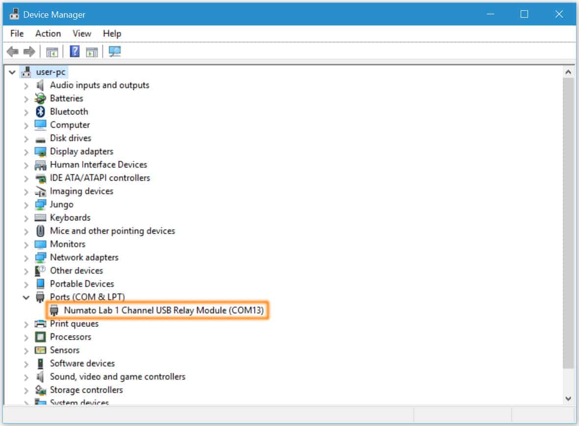
Note down the name of the serial port (COM1, COM2, etc..). This information is required to control the module from the PC.
You may notice that the driver package does not come with a .sys or .exe file as most driver packages do and are expected to be that way. The driver binary necessary in this case is shipped with all copies of Windows Desktop/Server editions and gets installed automatically while Windows is installed for the first time. The .inf and .cat files present in the driver package downloaded from http://numato.com merely associate this pre-existing driver with the attached Numato Lab device.
The following video demonstrates how to install the driver on Windows 10.
Installing on Windows Embedded Editions
Windows Embedded editions do not install the infrastructure necessary for the USB CDC by default in favor of a smaller footprint. This will cause the driver to install to fail unless the necessary files are manually installed prior to installing the driver. Please follow the steps below to install the prerequisites and drivers correctly. These steps are tested on Windows 7 Embedded Edition.
- Locate winemb-inf-mdmcpq.cab on Win 7 Embedded DVD/ISO image
- Copy winemb-inf-mdmcpq.cab to a folder Ex: C:Temp
- Run command DISM.exe /online /Add-Package /PackagePath:C:Temp
- Wait for Windows to restart (Restart machine manually if DISM does not restart the machine automatically)
- After reboot is complete, plug the device to a USB port and install driver normally (Driver is available for download at the product page)
Installing on Linux
To use any device that uses the USB CDC protocol with Linux, the USB CDC driver needs to be compiled into the kernel. Fortunately, most Linux distributions (Ubuntu, Redhat, Debian, etc..) have this driver pre-installed. The chances of you requiring to rebuild the kernel to include the USB CDC driver is very slim. When connected to a Linux machine, this product should appear as a serial port under /dev directory. Usually, the name of the device will be ttyACMx or similar. The name may be different depending on the Linux distribution you have. The image below shows the result of ls /dev command on a Linux Mint system with a USB GPIO/Relay device attached.
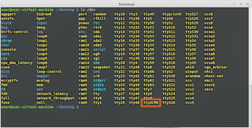
In this particular case, the device shows up as ttyACM0 (highlighted in orange color) but it could be ttyACM1 or ttyACM2, etc… depending on the specific system and other connected devices. Once the device is visible under /dev directory, it can be treated just like any other serial device. Commands can be sent to the device using any mechanism that is valid for regular serial ports such as screen command or Serial Terminal Emulation applications. If there is more than one device connected to the same host computer, each device will be displayed as separate serial devices with unique names. These separate serial devices can be used to control individual devices attached.
Installing on Mac OSX
Mac OSX is usually shipped with USB CDC driver pre-installed. When connected to a Mac computer, this product should appear as a serial port under /dev directory. Usually, the name of the device will be tty.usbserialportx or similar. The name may be different depending on the Mac OSX version you have. The image below shows the result of ls /dev/*usb* command on a Mac OSX Yosemite system with a USB GPIO/Relay device attached.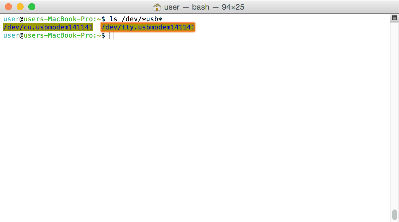
In this particular case, the device shows up as tty.usbmodem141141 (highlighted on orange color) but it could be any name starting tty.usbmodem or even a completely different name depending on the exact version of operating system and other connected devices. Once the device is visible under /dev directory, it can be treated just like any other serial device. Commands can be sent to the device using any mechanism that is valid for regular serial ports such as screen command or Serial Terminal Emulation applications. If there is more than one device connected to the same host computer, each device will be displayed as separate serial devices with unique names. These separate serial devices can be used to control individual devices attached.
Installing CDC Devices On Android
Most Android versions have a built-in driver that supports external USB Devices. Due to the presence of a built-in driver any external USB device including Numato Lab’s USB GPIO/Relay products connected to Android-based gadget will be enumerated by Android OS. Such enumerated devices can be listed/viewed by using apps such as USB Device Info. The image below shows info about a Numato Lab USB device printed by the USB Device Info app. All Numato Lab’s USB GPIO and USB Relay modules will be displayed the same way.
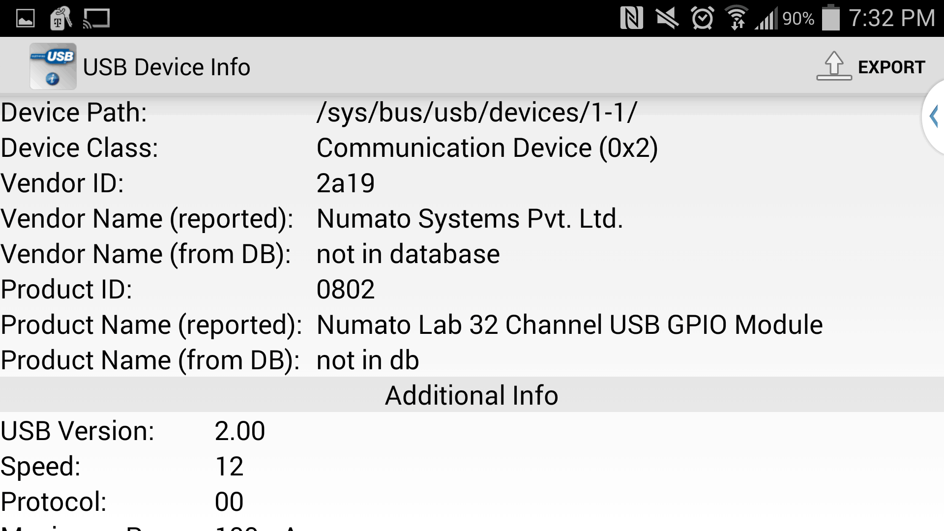
Devices detected by Android can be controlled by using an off the shelf Serial Terminal App such as USB Serial Terminal Lite.
Supported Error Codes
The LEO CG 16 Channel USB GPIO Module returns error codes to indicate invalid commands or incorrect parameter usage.
These codes help in quickly identifying and resolving issues during operation.
| Error Code | Error Name | Description |
|---|---|---|
| -3 | Invalid Command | The device does not recognise the entered command |
| -2 | Invalid Argument | One or more parameters are incorrect |
| -51 | Invalid Output Timer Limit | Timer delay is outside the allowed range |
| -41 | Invalid Smart Engine Mode | The IO is already set to a different smart engine mode |
| -42 | Invalid Output Value | The output value is outside the allowed range in the smart action engine |
Notes:
- Error codes are returned immediately upon command validation failure
- Ensure all commands and parameters follow the defined format and limits
- Refer to individual command sections for valid parameter ranges
Sending Commands
One of the most powerful features of this module is the simple easy to use command set it supports. This command set hides the complex USB protocol and gives a very simple interface to access the features of the module. The following sections give details of the command set and how to use the command set.
The command set
This product support a very simple command set that is designed to be less cryptic and easy to use manually (using serial terminal emulation programs) or through a program written in many supported languages.
List of currently supported commands.
| No. | Command | Parameters | Example | Description |
|---|---|---|---|---|
| 1 | ver | None | ver | Returns firmware Version |
| 2 | id | get/set xxxxxxxx | id get, id set 12345678 | Reads/Sets id of the module |
| 3 | usr | get/set xxxxxxxx | usr get, usr set admin | Reads/Sets User name |
| 4 | pass | get/set xxxxxxxx | pass get, pass set admin | Reads/Sets Password |
| 5 | usr auth | get/on/off | usr auth get, usr auth on, usr auth off | Returns User Auth status, Enable/Disable Authentication |
| 6 | smart | get/-i/-o/disable/ [input] [mode] [target_output] [value] | smart get 000, smart -i 000, smart -o 000, smart disable, smart 000 L 000 1 | Read configured data, clear configured input, disable entire smart action feature, configure smart feature |
| 7 | gpio | set/clear/read/status [gpio number]/status/writeall/iomask/iodir [value]/notify/poweron [iodir value] [gpio value]/iodir/iomask/write [gpo_group] [gpo_map] | gpio set 000, gpio clear 000, gpio read 000, gpio status 000, gpio status, gpio status, gpio writeall ff, gpio iodir 00, gpio iodir A 0000, gpio iodir, gpio iomask, gpio notify on, gpio notify off, gpio notify get, gpio poweron 00 ff, gpio write A 00ff, | Control and monitor the GPIOs |
| 8 | adc | read [adc number] | adc read 000 | Read Analog to Digital Converter input value |
| 9 | pwm | status, freq xxx y, duty xxx y, disable, status/on/off xxx | pwm status, pwm freq 000 1000, pwm duty 001 50, pwm disable, pwm status 000, pwm on 001, pwm off 001 | Control and monitor the PWMs. |
| 10 | fs | get input_number/reset/disable/ [input] [mode] [gpo_group] [gpo_map] | fs get 000, fs reset, fs disable, fs 000 L A 0012 | Read status of IO failsafe, Manual Reset Failsafe, Disable Failsafe, Configure Failsafe |
| 11 | info | none | info | Display information about the module including Smart Action, Power-on status, and IO Failsafe |
| 12 | reboot | none | power reset | Power reset does a soft-reset. |
| 13 | fact | reset | fact reset | Perform device factory reset |
The table below has more detailed information about available commands.
Device Command Set
| No. | Command | Example | Description |
|---|---|---|---|
| 1 | ver | ver | This command returns the current firmware version of the device. Command Format verResponse Format xxxxxxxx – Firmware version string Description Returns the firmware version currently running on the device. Example ver Returns firmware version Notes The version format may vary depending on the firmware release. |
| 2 | id | id get id set xxxxxxxx | This command is used to read and configure the device ID. Command Format id get id set xx – New device ID (exactly 8 characters) Description id get returns the current device ID. id set x updates the device ID to the specified value.Example id get Returns the current device ID id set DEV12345 Sets the device ID to "DEV12345"Notes The device ID must be exactly 8 characters in length. Changing the device ID may affect identification in connected systems or applications.n a new ID to the module. “x” stands for alphanumeric characters including symbols. The new ID must be exactly 8 characters in length. |
| 3 | usr | usr get usr set xxxxxxxx | This command is used to read and configure the device username. Command Format usr get usr set xx – New username (1 to 8 characters) Description usr get returns the current username configured on the device. usr set x updates the username to the specified value.Example usr get Returns the current username usr set admin Sets the username to "admin"Notes Username length must be between 9 and 31 characters. Changing the username affects authentication over the USB interface. It supports alphanumeric and symbols( !, @, ^, (, )) |
| 4 | pass | pass get pass set xxxxxxxxx | This command is used to read and configure the device password. Command Format pass get pass set xx – New password (9 to 31 characters, alphanumeric and symbols supported are !, @, ^, (, ))Description pass get returns the current password configured on the device. pass set x updates the device password to the specified value.Example pass get Returns the current password pass set admin1234 Sets the password to "admin1234"Notes Password length must be between 9 and 31 characters. Use a strong password to ensure secure access to the device. Changing the password affects authentication over the USB interface. |
| 5 | usr auth | usr auth get | This command returns the current USB authentication status. Command Format usr auth getResponse Format USR Authentication Disabled – Authentication is DISABLED USR Authentication Enabled– Authentication is ENABLED Description Returns whether USB authentication is currently enabled or disabled. Example usr auth get Returns USR Authentication Enabled if authentication is enabled, otherwise USR Authentication DisabledNotes Ensure authentication is enabled for secure operation. When disabled, commands can be executed without credentials. |
| usr auth on | This command enables USB authentication for the device. Command Format usr auth onDescription Enables authentication over the USB interface. Once enabled, valid credentials are required to execute commands. Example usr auth on Enables USB authenticationNotes Ensure valid username and password are configured before enabling authentication. If credentials are unknown, use factory reset to restore default access. |
||
| usr auth off | This command disables USB authentication for the device. Command Format usr auth offDescription Disables authentication over the USB interface. Once disabled, commands can be executed without requiring a username or password. Example usr auth off Disables USB authenticationNotes Disabling authentication reduces access security. It is recommended to use this feature only in trusted environments. |
||
| 6 | info | info | This command displays module information, including Smart Action status, Power-on configuration, and IO Failsafe status. Command Format infoDescription Returns a summary of key module configurations in a single response. Helps in quickly verifying system setup and operational status. Example info Returns module configuration summaryNotes The response format may vary based on firmware version. Use individual commands for detailed configuration of each feature. |
| 7 | reboot | reboot | This command performs a soft reset of the device. Command Format rebootDescription Restarts the device without altering any stored configuration. All settings, including Smart Action, Timer, Failsafe, and credentials, remain unchanged. Example reboot Performs a device soft resetNotes The device will briefly disconnect and restart after execution. Use this command to recover from temporary issues or apply configuration changes. |
| 8 | fact reset | fact reset | This command performs a factory reset of the device. Command Format fact resetDescription Restores the device to factory default settings. All configurations, including Smart Action, Timer, Failsafe, credentials, and other user-defined parameters, will be erased. Example fact reset Performs a device factory resetNotes The device will briefly disconnect, the LED will blink during the reset process, and the device will restart upon completion. Use this command to recover the device or reset all configurations. This action cannot be undone. |
GPIO/ADC/PWM Command Set
| No. | Command | Example | Description |
|---|---|---|---|
| 1 | gpio | gpio status xxx | This command returns the current status of a specific GPIO channel. Command Format gpio status xxxxxx – GPIO number (Range: 000 to 015, numbering starts from 0) Response Format 0 or 11 – GPIO is High 0 – GPIO is Low Description Returns the current state of the selected GPIO channel. Example gpio status 000 Returns status of GPIO 0Notes Ensure the GPIO number is within the valid range (000–015). The response reflects the real-time state of the GPIO at the moment of execution. |
| 2 | gpio status A | This command reads the current status of all GPOs in group A in a single operation. Command Format gpio status AResponse Format A:XXXXXXXX – Current GPIO state (hexadecimal value) Description The returned value represents the state of all gpios in the selected group. Each bit corresponds to one gpio channel. 0 – GPIO low 1 – GPIO high Example A:0000 – All GPIOs are low A:00FF – All GPIOs are highGroup Representation A – Group A (first 16 GPIOs) Each bit represents one GPIO channel Value Range 0000 to 00FF (8-bit) |
|
| 3 | gpio status | This command reads the current status of all GPIOs in a single operation. Command Format gpio statusResponse Format A:XXXXXXXX – Current GPIO state (hexadecimal value) Description The returned value represents the state of all gpios in the selected group. Each bit corresponds to one gpio channel. 0 – GPIO low 1 – GPIO high Example A:0000 – All GPIOs are low A:00FF – All GPIOs are highGroup Representation A – Group A (first 16 GPOs) Each bit represents one GPIO channel Value Range 0000 to 00FF (8-bit) |
|
| 4 | gpio set xxx | This command sets a specific GPIO channel HIGH. Command Format gpio set xxxxxx – GPIO number (Range: 000 to 015, numbering starts from 0) Description Set to HIGH the selected GPIO channel. Example gpio set 000 GPIO 0 set to HIGHNotes Ensure the GPIO number is within the valid range (000–015). The command immediately updates the GPIO state. |
|
| 5 | gpio write A xxxx | This command sets the output state of GPIOs in Group A in a single operation. Command Format gpio write A xxxxA – Group identifier (Group A represents the first 8 GPIO channels). xxxx – 8-bit hexadecimal value (Range: 0000 to 00FF). Do not prepend `0x` to the value. Description Sets the output state of all 8 GPIO channels in Group A simultaneously based on the specified hexadecimal value. - **0** – Sets the corresponding GPIO output to LOW. - **1** – Sets the corresponding GPIO output to HIGH. Examples gpio write A 0000Sets all GPIO outputs in Group A to LOW. gpio write A 00FFSets all GPIO outputs in Group A to HIGH. Notes Each bit in the hexadecimal value corresponds to a GPIO channel in Group A. Ensure the corresponding GPIO channels are configured as outputs before executing this command. |
|
| 6 | gpio clear xxx | This command clears a specific GPIO channel LOW. Command Format gpio clear xxxxxx – GPIO number (Range: 000 to 015, numbering starts from 0) Description Clear to LOW the selected GPIO channel. Example gpio clear 000 GPIO 0 clear to LOWNotes Ensure the GPIO number is within the valid range (000–015). The command immediately updates the GPOO state. |
|
| 7 | gpio set all | This command sets HIGH all GPIO channels. Command Format gpio set allDescription Turns ON all GPIOs in a single operation, regardless of their current state. Example gpio set all Sets High all GPIOS.Notes This command immediately sets all GPIO outputs to High. It overrides any previously set GPIO states. If a GPIO is mapped to GPIO timer, manual control will be restricted |
|
| 8 | gpio clear all | This command clears to Low all GPIO channels. Command Format gpio clear allDescription Clears to Low all GPIOs in a single operation, regardless of their current state. Example gpio clear all Clears to Low all GPIOsNotes This command immediately sets all GPIO outputs to Low. It overrides any previously set GPIO states. If a GPIO is mapped to GPIO timer, manual control will be restricted |
|
| 9 | gpio pwron A xxxx XXXX | This command sets the poweron value to GPIOs in group A. Command Format gpio pwron A xxxx XXXXxxxx – GPIO direction [0 – output, 1 – input] XXXX –poweron value [0 – Clear GPIO, 1- Set GPIO] Description Sets the GPIO status on power-on according to the hexadecimal value and IO direction mentioned. gpio poweron 000f 005d Example ‘000f’ ‘005d’ – 0000 0000 0000 1111 0000 0000 0101 1101GPIOs 0 to 3 – input GPIOs 4 to 15 – output Set GPIOs 0,2,3,4&6, Clear GPIOs 1,5,7 - 15 |
|
| 10 | gpio pwron get | This command returns the power-on output state configured for all GPIO channels. Command Format gpio pwron getResponse Format Poweron Value : xxxxxxxx – 8-bit hexadecimal value (Range: 0000 to 00FF). Description Returns the power-on value configured for the GPIO channels, indicating the output state each GPIO assumes when the module is powered on. Example gpio pwron getReturns Poweron Value: 00F3Indicates that GPIO 0, 1, and 4-7 are configured HIGH, while the remaining GPIOs are configured LOW on power-on. Notes Each bit in the hexadecimal value corresponds to a GPIO channel: - **1** – GPIO is configured HIGH on power-on. - **0** – GPIO is configured LOW on power-on. |
|
| 11 | gpio pwron disable | This command disables the GPIO power-on feature. Command Format gpio pwron disableDescription Disables the power-on feature configured for the GPIO channels. Once disabled, the GPIOs will no longer be set to their configured power-on values when the module is powered on. Example gpio pwron disableDisables the power-on feature for all GPIO channels. Notes Disabling this feature does not erase the previously configured power-on values. |
|
| 12 | gpio read xxx | This command returns the current status of a specific GPIO channel. Command Format gpio read xxxxxx – GPIO number (Range: 000 to 015, numbering starts from 0) Response Format 0 or 11 – GPIO is High 0 – GPIO is Low Description Returns the current state of the selected GPIO channel. Example gpio read 000 Returns status of GPIO 0.Notes Ensure the GPIO number is within the valid range (000–015). The response reflects the real-time state of the GPIO at the moment of execution. |
|
| 13 | gpio iodir | This command returns the I/O direction status of the GPIO channels. Command Format gpio iodirResponse Format IO Direction : xxxxxxxx – I/O direction value (Range: 0000 to FFFF) Description Returns the I/O direction configuration of the GPIO channels, indicating whether each GPIO is configured as an input or output. Example gpio iodirReturns IO Direction: 00F3Indicates that GPIO 0, 1, and 4–7 are configured as inputs, while the remaining GPIOs are configured as outputs. Notes The returned value represents the I/O direction configuration of all GPIO channels. Each bit corresponds to a GPIO channel, indicating its configured direction. |
|
| 14 | gpio iodir A | This command returns the I/O direction status of GPIOs in Group A. Command Format gpio iodir AResponse Format IO Direction : xxxxxxxx – I/O direction value (Range: 0000 to FFFF) Description Returns the I/O direction configuration of the 8 GPIO channels in Group A, indicating whether each GPIO is configured as an input or output. Example gpio iodir AReturns IO Direction: 00A3Indicates that GPIO 0, 1, 5, and 7 are configured as inputs, while GPIO 2, 3, 4, 6 and 8-15 are configured as outputs. Notes The returned value represents the I/O direction configuration of all 16 GPIO channels in Group A. Each bit corresponds to a GPIO channel and indicates its configured direction. |
|
| 15 | gpio iodir A xxxx | This command sets the I/O direction of all GPIO channels in a single operation. Command Format gpio iodir xxxx – 8-bit hexadecimal value (Range: 0000 to FFFF). Do not prepend `0x` to the value. Description Configures the direction of all GPIO channels simultaneously based on the specified hexadecimal value. - **0** – Configures the corresponding GPIO as an output. - **1** – Configures the corresponding GPIO as an input. Example gpio iodir A 0000Sets all GPIO channels as outputs. gpio iodir A ffffSets all GPIO channels as inputs. Notes - The GPIO direction must be configured using the `gpio iodir A xxxx` command before using the `gpio read` and `gpio set all` commands. - The direction configured using the `iodir` command may be modified by subsequent `set`, `clear`, or `read` commands. This applies only to the GPIO channels accessed through these commands. |
|
| 16 | gpio iomask | This command returns the I/O direction status of all GPIO channels. Command Format gpio iomaskResponse Format IO Direction : xxxxxxxx – I/O direction value (Range: 0000 to FFFF) Description Returns the I/O direction configuration of all GPIO channels, indicating whether each GPIO is configured as an input or output. Example gpio iodirReturns IO Direction: 00F3Indicates that GPIO 0, 1, and 4–7 are configured as inputs, while the remaining GPIOs are configured as outputs. Notes Each bit in the hexadecimal value represents the direction of a corresponding GPIO channel: - **0** – GPIO configured as output. - **1** – GPIO configured as input. The response reflects the current I/O direction configuration of the GPIO channels. |
|
| 17 | gpio iomask A | This command returns the I/O mask status of GPIOs in Group A. Command Format gpio iomask AResponse Format IO Mask : xxxxxxxx – I/O mask value (Range: 0000 to FFFF) Description Returns the I/O mask configuration of the 16 GPIO channels in Group A, indicating which GPIOs are enabled (unmasked) or disabled (masked). Example gpio iomask AReturns IO Mask: 00AAIndicates that the GPIOs corresponding to the set bits (1) are unmasked (enabled), while the GPIOs corresponding to the cleared bits (0) are masked (disabled). Notes Each bit in the hexadecimal value corresponds to a GPIO channel in Group A: - **1** – GPIO is unmasked (enabled). - **0** – GPIO is masked (disabled). |
|
| 18 | gpio iomask A xxxx | This command sets the mask/unmask status of all GPIO channels in a single operation. Command Format gpio iomask xxxxxxxx – 16-bit hexadecimal value (Range: 0000 to FFFF). Do not prepend `0x` to the value. Description Configures the mask/unmask status of all GPIO channels simultaneously based on the specified hexadecimal value. - **0** – Masks (disables) the corresponding GPIO. - **1** – Unmasks (enables) the corresponding GPIO. Examples gpio iomask 0000Masks all GPIO channels. gpio iomask FFFFUnmasks all GPIO channels. Notes Each bit in the hexadecimal value corresponds to a GPIO channel. A set bit (1) enables the corresponding GPIO, while a cleared bit (0) disables it. |
|
| 19 | gpio notify on | This command enables digital input (GPIO) change notifications. When enabled, the device monitors input state changes and sends a notification to the host whenever a change is detected. Command Format gpio notify onNotification Format A:XXXX/YYYYXXXX – Current input state YYYY – Previous input state Description A notification is sent only when a change is detected in any input bit. The value represents the state of all inputs in the group using hexadecimal format. Example A:00FE/00FF Previous state: 00FF Current state: 00FE This indicates that GPIO 0 changed from HIGH (1) to LOW (0), triggering the notification. Group Representation A – Group A (first 16 digital inputs) Each bit represents one input channel 0 – GPIO LOW 1 – GPIO HIGH Value Range 0000 to FFFF (16-bit) |
|
| 20 | gpio notify off | This command disables the GPIO change notification feature. Command Format gpio notify offResponse Format Gpio Notify DisabledDescription Disables automatic notifications for digital input state changes. Once disabled, the device will no longer send updates to the host when input states change. Example gpio notify off Disables GPIO change notifications |
|
| 21 | gpio notify get | This command returns whether the GPIO change notification feature is enabled or disabled. Command Format gpio notify getResponse Format Gpio Notify Enabled or Gpio Notify DisabledDescription Returns the current status of the gpio change notification feature. Example gpio notify get Returns Gpio Notify Enabled or Gpio Notify Disabled |
|
| 22 | adc | adc read xxx | This command reads the analog value from a specific ADC input channel. Command Format adc read xxxxxx – ADC input channel number (Range: 000 to 007) Response Format 0 to 1023Description Reads the analog voltage present at the selected ADC input and returns its corresponding digital value in the range of 0 to 1023. Examples adc read 000Reads the analog value from ADC input 0. adc read 004Reads the analog value from ADC input 4. Notes Ensure the ADC input channel number is within the valid range (000–007). The returned value represents the analog input voltage converted into a 12-bit digital value. |
| 23 | pwm | pwm status | This command returns the current status of all PWM channels in a single operation. Command Format pwm statusResponse Format A:XXXXA – Group identifier (Group A represents the first 16 PWM channels). XXXX – Current PWM channel state (16-bit hexadecimal value, Range: 0000 to FFFF). Description Returns the current output state of all PWM channels in Group A. Each bit in the hexadecimal value corresponds to one PWM channel. - **0** – PWM channel output is LOW. - **1** – PWM channel output is HIGH. Examples A:0000Indicates that all PWM channels are LOW. A:FFFFIndicates that all PWM channels are HIGH. Notes Each bit in the 16-bit hexadecimal value represents the output state of a corresponding PWM channel in Group A. |
| 24 | pwm status xxx | This command returns the current status of a specific PWM channel. Command Format pwm status xxxxxx – PWM channel number (Range: 000 to 015, numbering starts from 0). Response Format 0 or 1- **1** – PWM channel is HIGH. - **0** – PWM channel is LOW. Description Returns the current output state of the selected PWM channel. Example pwm status 000Returns the status of PWM channel 0. Notes - Ensure the PWM channel number is within the valid range (000–001). - The response reflects the real-time output state of the PWM channel at the moment of execution. |
|
| 25 | pwm freq xxx y | This command sets the operating frequency of a specific PWM channel. Command Format pwm freq xxx yParameters - **xxx** – PWM channel number (000 or 001). - **y** – Desired PWM frequency in Hz. - **PWM 000:** 1 Hz to 5 MHz. - **PWM 001:** 1000 Hz to 5 MHz. Description Sets the operating frequency of the selected PWM channel. The specified frequency must be within the supported range for that channel. Examples pwm freq 000 1000Sets the frequency of PWM channel 000 to 1 kHz. pwm freq 001 5000000Sets the frequency of PWM channel 001 to 5 MHz. Notes - Ensure the PWM channel number is either 000 or 001. - Specify the frequency in Hz and ensure it is within the supported range for the selected channel. |
|
| 26 | pwm duty xxx y | This command sets the duty cycle of a specific PWM channel. Command Format pwm duty xxx yParameters - **xxx** – PWM channel number (000 or 001). - **y** – Desired duty cycle (Range: 0 to 100%). Description Sets the duty cycle of the selected PWM channel. The duty cycle determines the percentage of time the PWM signal remains HIGH during one complete cycle. Examples pwm duty 000 50Sets the duty cycle of PWM channel 000 to 50%. pwm duty 001 75Sets the duty cycle of PWM channel 001 to 75%. Notes - Ensure the PWM channel number is either 000 or 001. - Specify the duty cycle as a percentage between 0 and 100. |
|
| 27 | pwm on xxx | This command enables the PWM output of a specific channel. Command Format pwm on xxxParameters - **xxx** – PWM channel number (000 or 001). Description Enables the PWM output on the selected channel using the previously configured frequency and duty cycle. Example pwm on 000Enables the PWM output on channel 000. Notes - Ensure the PWM channel number is either 000 or 001. - Configure the desired frequency and duty cycle before enabling the PWM output. |
|
| 28 | pwm off xxx | This command disables the PWM output of a specific channel. Command Format pwm off xxxParameters - **xxx** – PWM channel number (000 or 001). Description Disables the PWM output on the selected channel. Example pwm off 000Disables the PWM output on channel 000. Notes Ensure the PWM channel number is either 000 or 001. |
|
| 29 | pwm disable | This command disables PWM functionality on all available PWM channels. Command Format pwm disableDescription Disables the PWM output on all available PWM channels, stopping their PWM signal generation. Example pwm disableDisables all PWM channels. Notes This command disables PWM functionality on all available channels, regardless of their individual configuration. |
Additional Information
Using GPIO's with switches
It is possible to read the position of a switch that is connected to a GPIO. A SPST or SPDT switch is recommended to use with GPIO’s. Push switches do maintain the contacts closed only for a very short time so using them is 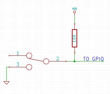 discouraged. The fundamental idea of using a switch with GPIO is to have the switch cause a voltage level change at the GPIO pin when pressed. Usually this is achieved by using an external pull-up resistor along with the switch. The pull up resistor is connected between the GPIO and VDD and the switch is connected between the GPIO and ground. When the switch is not pressed, the pull-up resistor will cause the GPIO to stay at VDD voltage level. When the switch is pressed, the GPIO is short circuited to ground and stays at zero voltage. This change in voltage and thus the position of the switch can be read using “gpio read” command. Please see the recommended connection diagram below
FAQ
Q. I need a customized version of this product, can Numato do the customization for me?
A. Yes, we can definitely do customization but there may be minimum order requirements depending on the level of customization required. Please write to sales@numato.com for a quote.
Q. Where can I buy this product?
A. All Numato products can be ordered directly from our web store http://www.numato.com. We accept major credit cards and Paypal and ship to almost all countries with a few exceptions. We do have distributors in many countries where you can place your order. Please find the current list of distributors here.